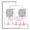
So I'm going to start my headlight wiring upgrade and I bought everything I need:


2 - 30 amp Five pin relays so I don't have to wire up a pigtail for the hi/low beam wire

2 - High Heat H4 connectors to replace the lesser quality ones on the car now

1 - Male H4 connector to plug into the existing H4 connector on the car so I don't have to cut up the wiring

Plenty of 14ga red, black, and blue wiring, connectors, and heat shrink tubing


I am attaching the diagram I found and will follow unless someone tells me it is not correct. Since I'm using the 5 pin relays I will have a two pins on each relay to send power out to the right and left headlight. So for my low beam relay there are two pins for sending power out, one for each side. The high beam relay will also have two pins for sending power out to each light also.


With the likely increase in heat from the H4 lamps is there any reason I couldn't/shouldn't drill holes in the back of the fiberglass headlight recess to allow heat to escape?

If you're not living life on the edge, you're taking up too much space!


Attachments

Images (1)
  • headlights2: Proposed Wiring Diagram
Last edited by Robert M
Original Post

Replies sorted oldest to newest

First, is there some reason you are not just using a standard headlight dimmer relay? Unless you were planning on using a toggle switch, you don't show anything there to work with a standard momentary-contact dimmer switch.


Is your 5-pin relay a standard 87/87a output or a dual 87 output? Only a dual 87 is going to work for connecting the left and right separately to the relay as you intend. But other than not having to fit 2 wires on the same connector, I don't think there's any real benefit to it.


I have no idea what the "old headlight plug" goes to to actually control the relays.


Why do you have that diode in there? You don't need both low beam and high beam filaments active at the same time. Besides extra heat which could reduce the bulb life, the added light close to the car from the low beams will make it harder for your eyes to see things that the high beams are supposed to illuminate. That is, it will appear brighter but your max viewing distance will actually be less.

Last edited by justinh

@ justin


Whoops, should have stated I wouldn't be using the diode either. That was something some 4x4 guys were doing. And the relay is a dual 87 not 87/87a.


I was going to use the old headlight female connector plug to power the relays. Wire the low beam power to one relay and the hi beam power to the other relay. Instead of cutting off the connector I was going to plug a male connector into the old headlight plug.

The standard VW headlight dimmer relay, VW part # 111-941-583, or could be listed as DNI 0127, or Napa part # AR284, will work with a momentary-contact switch (standard VW dimmer switches). And it can carry the current for the new lights just fine by itself without needing separate extra relays for high and low. For example, the DNI0127 is rated at 25 amps @ 12V = 300 watts. I think you are overcomplicating things.

Last edited by justinh

"could you use an American 60s floor dimmer switch wired to the push button under the dash on a VS?


Absolutely.........That would be about the most American thing you could do on these cars, short of putting a V8 into them.  


But the original Porsches had the (much more practical) dimmer and high beam flasher on the steering column in, what?.....1953?  Something that the American iron didn't finally get right until the late 1990's and even then they couldn't agree between manufacturers as to how to do it right (and VW had it right all along).


So, Could you use a floor dimmer foot button?  Sure.  Nobody will laugh at you.....I promise.  


BTW:  I'm grumpy from riding a fast-ish 34 mile bicycle ride later this afternoon, but both of those wiring diagrams up above supposedly depicting a "normal" hi/lo headlight circuit make about as much sense as plain Grits.


I'll try to find a decent headlight wiring diagram after dinner and post it for you.

Last edited by Gordon Nichols

OK, so I have now eaten and re-stabilized my blood-sugar levels and downed a couple of Sam Adams Summer Lagers.


Re-looking at Bob's schematic shows me that, (a.) it uses a lot of what's already there and (b.) the damn thing should work.  Just shows to go what a little food and a couple of beer-replenishments can do for an ancient biker body.


Bob!  The only cautionary thing I can think of is the really tight clearance between the inside of the headlight bucket and the back end of the headlight plug.   I had a lot of trouble getting one thin enough to fit between the headlight and the inside of the bucket.  Once I got that squared away, everything fit, went together well and worked. I think I used a Dorman or Echlin product, but can't remember which.  If you find plugs that fit, you're Golden, my friend.


Continue with your original plan.  It should work as hoped for.  Make the wire between the battery and the relay, and then the relay to the headlights as short as possible (be creative).  If possible, place a 15-20 amp fuse (depending on the current draw of your H4 bulbs) in-line between the battery and the relay +12V feed - that may prevent an overload and potential fire.


Other than that, Rave on, Dude!


gn

Last edited by Gordon Nichols

Thanks Gordon.


When I installed my new HELLA Horns I also installed a fuse block in the battery compartment area.  I have a heavy wire running from the battery to the block and I'll install fuses to power the relays.  I will be running a heavy wire from there to the relays.  I have been contemplating what to do about clearances inside the bucket area so I'll give that some more thought before tearing it up.


I may even cut the current H$ connector off and reassembling it outside the buck so there will only be one connector in there.  I know it seems redundant but I may enlarge the hole so I can feed it back into the bucket and fill the gap with a rubber grommet.

Robert.  A couple of questions.
1. Where did you find the 87/87 relay?  Napa acted like I was from Mars when I asked for that.

2. What % increase in brightness do you expect to realize from this upgrade?  Looks like a lot of work, for what might not even be a noticeable increase.  I know you really enjoy doing the work and that might be all that really matters, but I'll be anxious to hear what the real improvement is.

Napa AR274 is the part number and it has dual 87 output pins.


Here is the chart from http://www.danielsternlighting...s/relays.html :


In many cases, the thin factory wires are inadequate even for the stock headlamp equipment. Headlamp bulb light output is severely compromised with decreased voltage. The drop in light output is not linear, it is exponential with the power 3.4. For example, let's consider a 9006 low beam bulb rated 1000 lumens at 12.8 Volts and plug in different voltages: 


10.5V : 510 lumens
11.0V : 597 lumens
11.5V : 695 lumens
12.0V : 803 lumens
12.5V : 923 lumens
12.8V : 1000 lumens 
13.0V : 1054 lumens
13.5V : 1198 lumens
14.0V : 1356 lumens
14.5V : 1528 lumens


When I checked my lights I was someone in the neighborhood of 11.0V and possibly even lower.  By increasing the wire size and adding the relays I expect to move up the chart closer to what my battery/alternator actually put out.  Part of wanting to do this is so I can run a brighter bulb as well without melting the current wiring or burning out the headlight switch. I've been under the car and now that I've had a look at things again I don't suspect it will be too difficult. I expect it will be along the lines of adding the new horns.  I'll mount the relays next to the horn relay, bring in power from the new fuse block, pull wire to the headlight buckets, cover it all with black wire looms and voila! brighter lights.

Last edited by Robert M

Bob you are right - worth effort.  Most folks don't realize that efficiency (poor when brand new) of incandescent lights decreases each year and OSRAM recommends replacing every 2 years.  (The Sylvania OSRAM Silver Star H4 elements actually burnout after a year or so but are 50% brighter than sealed beams). I see old VWs go down road at night with what looks like dim yellow headlights.  The old thin wiring (most likely corroded with those crappy ceramic fuses) and a weak 30 amp generator contribute to weak lighting.  

Somewhere along the line I was upgrading someone's lights and couldn't find a thin-profile headlamp socket to fit inside the headlight bucket - just wasn't enough room to get the slightly thicker replacements (with 10ga wires) crammed in there, sooooooo.......  


I whipped out the hole saw and cut a hole in the back of the bucket big enough to fit the socket into as well as a recycled aerosol can plastic top sticking slightly out the back to accept the socket.  Gooped the cap in with silicon caulk (fortunately, it had a lip at the bottom) and let it set up, then just assembled everything.  No worries about the socket crammed against the back of the bucket and the new sockets have much heavier wires everywhere so no worries about heating up, either.  

Originally Posted by DannyP:

       
Troy, I got those relays for a buck each at a car stereo store. Napa and others may charge a lot more for these relays than is necessary for you to pay. I think I bought ten.....


Danny.  Are you sure they were 87/87 and not 87/87a?
I had never heard of 87/87 until I wired my fog lights recently.  I ended up using and 87/87a and just pigtailed it so both lights were being feed by the one relay.
Originally Posted by DannyP:
Power= voltage x current
60watts= 12v x 5amps
60watts= 14v x ~4.3amps

This isn't correct. A bulb's rating would be for example 60W @ 12V, from which you could estimate the expected current or resistance @12V as you've done in the second line. However, Watts are not a constant in that equation, so you can't use it to calculate the amps @14V. You have to calculate the resistance (2.4 Ohms) and then use that to calculate the amps @14V which would be 5.8 Amps, not 4.3. However, the resistance of the filament in the bulb increases non-linearly as it heats up so resistance isn't a constant either for calculation purposes. If you actually want to know what amps a 60W bulb draws at 14V (without having a reference graph from the bulbs datasheet) you'd have to just measure it.


As an example (from some random halogen bulb on the internet):

@10V = 4 A, so 40 Watts and 2.5 Ohms

@15V = 5 A, so 75 Watts and 3.0 Ohms

@12V looks to be around 55 Watts.


Last edited by justinh

I finished wiring everything up and it wasn't that bad.  I did however have some initial problems with something grounding out and blowing fuses.  I wasn't able to use the existing plug as the jumping off point for the new wiring harness.  The old plug was melted and stuck to the H4 bulb.  Some very careful nudging with a flat blade screwdriver separated the two pieces.


I cut off the old plug and hardwired everything together.  After I got it all together I had a problem with one of the original fuses popping so I had to trace out the problem.  I ended up having to splice into the original ground and connected that to the ground on the relays.  And then ground the headlights to the frame.


In the original test I had only 10.2 volts reading at the headlight plugs. Now I have 12.98 volts reading at the plugs so based on the chart for a 1000 lumen light I will not go from just under 510 lumens to just over 1000 lumens.


I'm also benefiting from much heavier wiring in my lighting system. I took photos using my Nikon camera set on Manuel Mode so the increase in lighting wouldn't affect the aperture or shutter speed. Here's the pictures I took before and after:

Attachments

Images (2)
  • DSC_0053: Before with 10.2 volts
  • DSC_0061: After with 12.98 volts
Last edited by Robert M

I took the Speedster out for a drive last night to test the new lights (wink, wink) and the reach of the new lights id impressive.  They will need some adjusting now since they don't fall directly directly in front of the car.


Anyway after a short drive I touched the glass in front of the lens and it wasn't very warm at all.  It was even less warm than before even with the lights being brighter. I felt all around the fiberglass that surrounds the headlight bucket as well and it was still cool to the touch.


When I switched on the high beams I would have sworn I heard several planes beginning their approach to land on my street there were that bright.

Post Content
×
×
×
×
Link copied to your clipboard.
×
×