Today I spent a couple hours on ECU assembly. I did quite a bit of soldering, thankfully I bought myself a nice temperature-controlled soldering station some years ago.
Those who don't want to read, skip to the pictures at the end. Summation: I did a LOT of soldering today.
I started out with the stepper driver for future idle valve control. It's all surface mount components on a board with 8 pins down each side, so soldering that in is like soldering an old 16 pin integrated circuit.
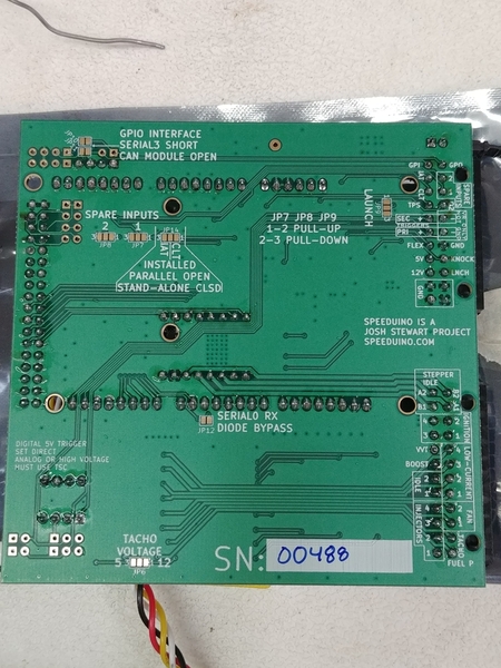
Then I soldered the connectors for the wiring harness, a 22 pin and a 24 pin. They were easy, the plastic connector snaps right to the board.
Then the rest is all header pins, but a LOT of them. The Arduino Mega has about 80 female contacts.
Then there were a few more for jumpers to select different options, and a 4 pin header for Bluetooth. 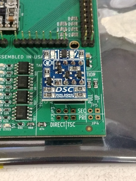
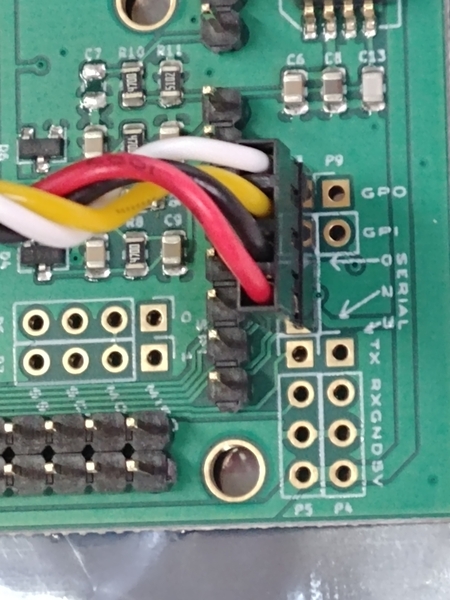
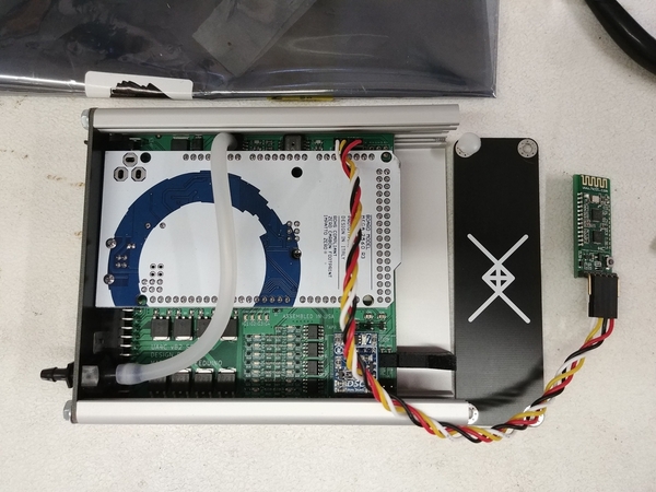
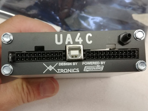
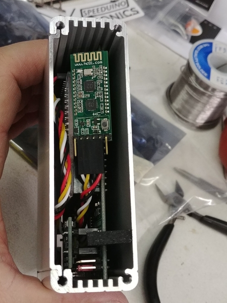
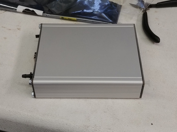
The Bluetooth board will get a heat-shrink on it and probably a dot of hot glue.
It's pretty cool that the board/case came with the vacuum bulkhead fitting and hose for the MAP sensor. It even comes with a 3D-printed plastic piece that keeps the board pushed toward the connector end of the case.
Tomorrow, firmware/software download and testing.


