My latest update. I've converted over to totally electronic ignition powered by Speeduino ECU and a VW Golf/Passat high energy electronic ignition coil pack. It works just fine. Additionally, the carb linkage was lowered to make room for the AC compressor and I've begun to install the shoulder harness seat belts. To begin, I built a mount for the Saab 900 crankshaft position sensor (CPS). I mounted it on a case bolt on the lower passenger side of the engine. It is a VR (variable reluctance) sensor so I'm using twisted pair to the Speeduino during the test phase and will wire it with shielded two or four pair in production. The Speeduino detects TDC from the CPS when the missing tooth wheel behind the crankshaft pulley skips a beat. For those who are trying this, in my case, I configured the Speeduino to identify TDC as 92 degrees before the missing tooth. This will vary depending on how you attach your missing tooth part to the pulley and the location of the sensor.
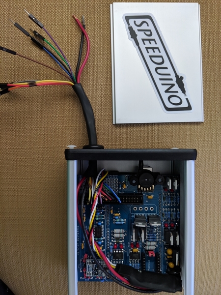
The brains. Configured using Tunerstudio via a bluetooth connection. I use Shadow Dash via bluetooth on my phone to monitor it while it's running.
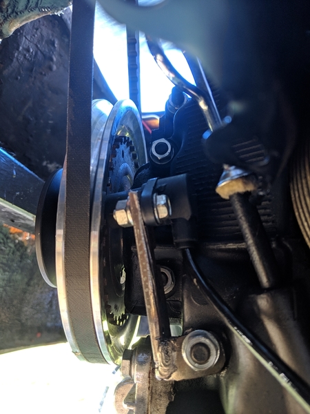
Here's a pic of the crankshaft position sensor bracket that I fabbed up. The sensor is at the top and leans in at an angle to pick up the rotation of the teeth on the missing tooth wheel I mounted behind the crank pulley.
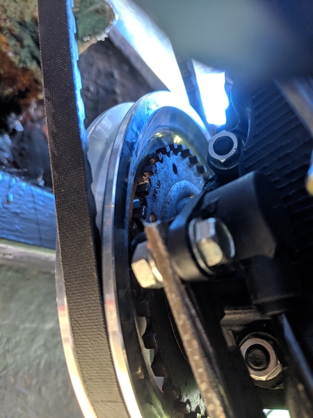
Here's a closer shot of the sensor itself. It's the black cylinder behind the shiny bolts at the top of the slightly rusty, bespoke bracket. Like I noted earlier, it leans in at an angle, but picks up the signal loud and clear.
I'm using MSD 8.5mm ignition wires with GM LS2 coil pack terminators on the coil side. They have great noise suppression as well has the ability to handle the high voltage produced by electronic ignitions. These are roughly 2 feet in length, each.
The very inexpensive Golf/Passat coil pack (part # 032905106B) is mounted on the firewall. It has 2 ignition inputs from the Speeduino and 4 spark outputs to the plugs. It is configured in Tunerstudio (software that drives the Speeduino) for wasted spark. This means that when the Speeduino senses that a spark is needed for input 1, the coil fires plugs 1 & 3. When input 2 is sensed, the coil pack fires plugs 2 and 4. For the cylinders that are not filled with compressed fuel/air, the spark is wasted, however, Jim Cortina with the Megasquirt project has bench tested this coil pack to over 13,000 rpm. I suspect it will work just fine for me. When I built my 425 hp Porsche turbo motor, I used a similar EDIS 6 wasted spark system with great results.
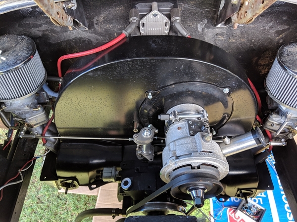
Wow, look at all of that empty space. Note the VW coil pack on the firewall above the shroud and the MSD wires routed out of the way of stray compressor bits. For those with discerning eyes, you may spot the lower third of a Bosch 009 that has been gutted and filled with J-B Weld.
The upshot is I was able to remove the distributor and free up a lot of space for the AC compressor while improving the accuracy and strength of the ignition system. Total system cost was under $300. I did a lot of fabrication for this and would highly recommend the Dub Shop kits for folks who are less inclined or less patient. I thought about this fact several times during the process.
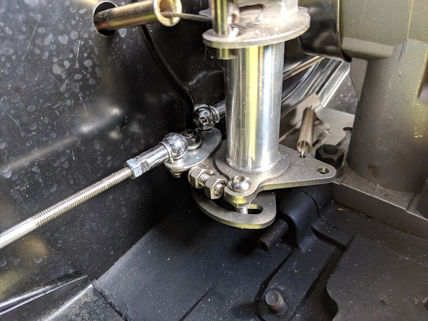
I'm using the Vintage Speed Taiwan's dual carb linkage and I decided I could get another inch or two clearance for the compressor by converting the left side linkage to a pull instead of the normal push. To do this, I make a small steel oval that attaches both the right and left sides to the attachment where the right side normally attaches (nearest the shroud). This means when accelerating, the linkage pushes the right side open (just like normal) and pulls the left side open. To make this work, I drilled and pinned the larger adjustment threaded part nearest the left carb. This allows it to be pulled. I then moved the carb linkage lever from the top side of the left carb to the bottom so the push will open the carb. Works great and is just as adjustable as the original. Now I've got plenty of space for AC. Yes, I love my wife. That's why AC is required.
The little oval at the back allows both linkage arms to be driven from the rear cam.
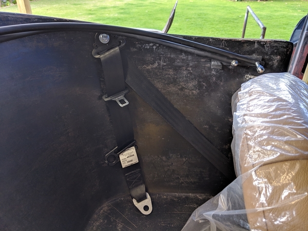
I'm installing retractable shoulder harness seat belts that I sourced from Greg and Anna at Vintage Motorcars. I've just started the installation, but have pretty much gotten my plan together. The real trick is that the shoulder belt support needs to be located higher than your shoulder to reduce the chance of injury. It's nice not to meet the steering wheel with your face, but you don't want a spine injury in exchange. I measured my shoulder height in the seat and then used a level to locate the spot on the back seat wall nearest the door that would allow an attachment with a steel backing plate. This was roughly 17.5" back from the top edge of the frame at the door. I drilled a bolt hole about 1.5" down from the top of the rear seat and then went underneath the body with various cutting tools to make room for curved plates that followed the shape of the back seat. These plates will be welded to the body frame with steel braces to reduce then chance that they'll pop through the fiberglass in an accident. The reels are attached right below the back seat lip and secured through the inverted "V" shaped steel beam that crosses the tunnel. I found that I needed to mount the reels as close to the doors as possible (and still feed cleanly). Otherwise, the mounting bolt comes out into the space where the body support heads back towards the engine. More pics on this will come later.
Seat belt should harness attachment above shoulder level. Reel is secured at front edge of rear seat, behind the driver's seat.
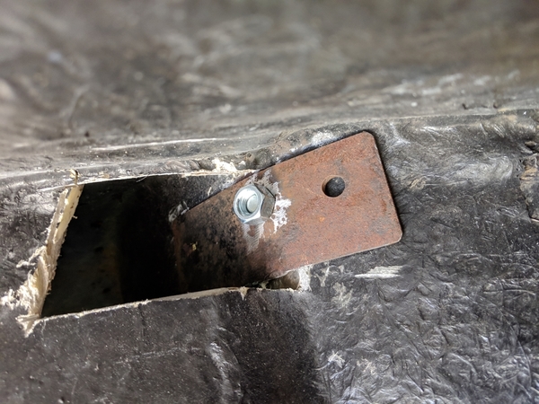
View of curved steel support behind rear seat. This pic was shot from inside the passenger side wheel well. The side fiberglass on either side of the engine had to be cut to extend the curved piece behind the rear seat. Additional bracing will be welded to the curved piece.
I know I've said it before, but thanks to everyone who has gone before and those who continue to advise and encourage. You've made it possible for seriously inadvisable projects to succeed.
Mike


