

Not to be hypocritical...
Here's Bridget's engine bundled up for the other machine shop. Sent it off with a neighbor today to get the block decked about 3-4 thousanths. The heads came back last week and, looking at them, compared to the mating surface on the block, I just could not in good conscience put it back together without doing this. Pretty sure I gruffed it up beyond eligible spec with the scotch brite pad in the drill, a trick Danny suggested but that I obviously goofed on—probably with a too-rough pad. Luckily, the neighbor's diesel engine rebuilding outfit has a pretty big mill, and they told me (contra what my regular machine shop required) that I did not have to tear the engine down to the bare case halves to get this job done.
Thoughts and prayers, men.
Here's the first rough CAD of the front half of my (proposed) rear engine underpan thingy. I made this the other day whilst nervously pondering Bridget's engine's fate, awaiting pick-up.


This is just a first mock-up. I have paused to consider how the airflow through the fan and the cylinders/heads needs to join the air flowing under the car. The J tubes from the Sebring exhaust run directly under the heads about a quarter inch below the pushrods. Tight. There are no sled tins on there now and I'm thinking my first task is to make those, tight over those exhaust pipes, and exit the air just behind the engine and duct it into the channels for the exhaust pipes there. Simple, right?
Here's what Wendler came up with—and a much easier job it was on a Type 547 engine, with its bottom-exiting pipes set conveniently in the middle of the heads.

Arjani's car is a bit harder to do than an original, since he has a Type 1 mill. . . 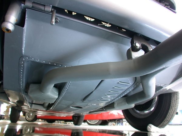
—But at least he has the correct S-shaped cross member mounting the enigine. On my car, it's straight and rectangular and situated right where I want to dump the hot air: basically another restriction or choke point in the perfect wrong spot.
And the second pipe there joins the party with a nice fat collector and a flange.

Looking at it tonight I can see the way forward (I think). But it's going to be some tricky duct-making, at best. . . .
At least the sway bar project is done. 