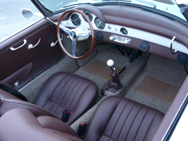
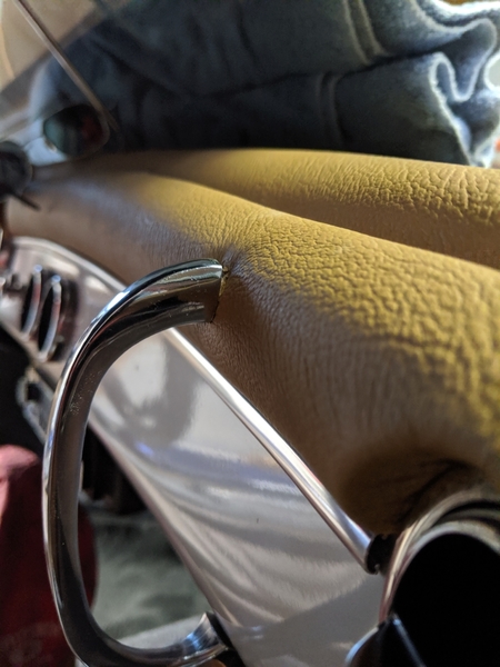
Thanks, I laid out the dash shortly after I began bringing the body back from the dead. I knew I wanted an outlaw so things just went where I felt like it made sense. It's not perfect (windshield washer button almost too close to the steering column), but when I look at it, it gives me the warm fuzziest. Thanks again for everyone's advice and encouragement. Next step is the cabrio top.
That lower panel that we see on A/C cars always looks like a tack-on. A nice tack on, but a tack-on nonetheless.
Even just the radio hung below the dash looks like a tack-on but What'cha gonna do? Not a lot of options available to us because of tight spaces and it looks like Mike has accomplished his vision with a very classy result. I hope to see a few copies of this in the future.
It's always nice to see a fresh take on how to personalize these cars, and Mike has been consistently hitting it out of the park.
Gordon Nichols posted:That lower panel that we see on A/C cars always looks like a tack-on. A nice tack on, but a tack-on nonetheless.
Even just the radio hung below the dash looks like a tack-on but What'cha gonna do? Not a lot of options available to us because of tight spaces and it looks like Mike has accomplished his vision with a very classy result. I hope to see a few copies of this in the future.
It's always nice to see a fresh take on how to personalize these cars, and Mike has been consistently hitting it out of the park.
^ Amen to that.
I did not see any interior lights ala IM style.
Here is and LED style of the same lights I have they are not as soft as a incadescent but if you wire them on the main light switch you could decide to turn them on from there &/or have the door switches operate them. $5


Attachments
IaM-Ray posted:I did not see any interior lights ala IM style.
Thanks for the sources, Ray. This body sat out by the ocean for 14 years and after that I had no idea about how it looked originally. I'll want some inside lighting and will pick up some of the ones you suggest. Stupid question, but where do they go?
Mike
Mike the chrome strip looks awesome IMO. ![]()
Wow!! Looks absolutely fantastic. Great job! ![]()
IaM-Ray posted:Hey Mike I finally found one, was not easy to find, it happens to be of my old IM. BLow it up a bit you will see it on the passenger side but there is one on both sides.
Got it. That's very helpful!
These are the incandescent ones that I believe IM uses:
http://www.vehiclesafetysupply...mp-61501-p-4094.html
You can also find them on ebay. The part is Grote 61501.
I got a pair of small "utility lights" at Autozone and mounted them to the crossmember behind the dash. IIRC, IM mounts a slightly fancier light to the tops of the side kickpanels. Six of one..........
If you have Autozone on your part of the island, here you go - Just the right size:
What's the thinking about switches for the interior lights? Door switches or a dedicated switch (maybe under the dash)? Thanks!
I'd do both.
The dedicated switch can be the light switch, if it's got a "twist left" position.
I just have the door switches 'cuz my headlight switch pre-dates the "twist-left" era. ![]()
The door switches are el cheapo self-adjusting, two-tab, NC jobbies, since the body doesn't ground. I got them at NAPA but couldn't find them in their online catalog.
Ask for an equivalent to Standard Motor Products DS-206, DS-240, or DS-452
I like the ones with a nylon button.
Gordon Nichols posted:I just have the door switches 'cuz my headlight switch pre-dates the "twist-left" era.
The door switches are el cheapo self-adjusting, two-tab, NC jobbies, since the body doesn't ground. I got them at NAPA but couldn't find them in their online catalog.
Ask for an equivalent to Standard Motor Products DS-206, DS-240, or DS-452
I like the ones with a nylon button.
Perfect. Napa is my local option. Thanks!
My IM has door switches that are pretty nice but they may be too short I installed stick on cushions to make them contact more fully.
I think I found it .. https://www.ebay.ie/itm/Door-h...-metal-/261774739926
Is this close to you Mike? Sorry I saw Oz, but it is in the UK. At least you know the style now.

Attachments
There are some much less expensive switches but I am not sure the oval plate is available on those. Just saying.
Help, I need dash grab bar that will fit dashboards with the IM/CMC bumpers. Does anyone know where I might find one?
Thanks!
Post a picture of the one you have.
Same no difference
IaM-Ray posted:
Is this what your looking for

Yep. You have the same thick rubber bumper. The handle I bought doesn't match up with the original holes in the dash and rubber.
Alan Merklin posted:Same no difference
You mean it's the same handle? The holes matched up without the rubber bumper but is way off with the bumper attached.
Attachments
Weird. I positioned the dash rubber using the original holes in the rubber and the dash. The original grab bar must have gotten lost in in the 14 years that it sat so I don't have a comparison.
If Alan says they're the same, it's good enough for me. I can redrill the hole under the dash and stretch the leather downward and make it look decent if I put a big gasket up top.
Attachments
Ok, working on the top installation. I was inspired by the fact that it sprinkled rain at our house yesterday. The winds had shifted and were coming from the south. That meant that the 10,000 foot Haleakala wasn't shielding us from the normal rains you get out in the Pacific. We call the south winds "Kona winds" since the west coast of the big island is to our south. In any event, Maui gets lots of rain everywhere but where we live, so a top is a good idea.
Everything is proceeding well. Great instructions from Gordon, Alan and others. The header bow has been glued and now the edge of the fabric has been flipped over inside the bow and glued. It is in the process of drying.
Fortunately, I had previously sourced some bespoke, custom German wooden clips that were in limited use during the construction of the original Porsche 356s. They are designed to hold the fabric against the glue inside the header bow as it dries. This ensures a crisp, taut edge of fabric against the bow and prevents wrinkles that might besmirch my concours aspirations. Looks like it's working out as planned...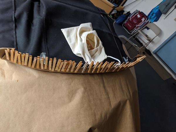
Attachments
Attachments
Screechy engine noises not related to slipping fan belts. I heard a short, disturbing screechy noise and there started to be oil drips from the pulley area. I pulled the crank pulley and fished out the washer behind it... Wait a minute, there is no washer behind the pulley, only the oil slinger. Somehow, the oil slinger got torn into two parts, a washer size part and a larger ring that is loose, but too large to come out of the crank nose hole. Don't I have the most unusual challenges...
I haven't figured out what caused the slinger to tear apart. Anyone else ever seen this? The engine sat new, but unrun, for twelve years before I bought it. I've put 175 miles on the engine in the last month or so. No obvious large debris in the crankshaft nose area.
In any event, I'm pulling the engine and will split the case in the next day or so to see what's going on and what it will take to put things right. The best scenario is a cleanout and just replacing the slinger and maybe the rear main bearing. When I drained the oil, no big chunks of anything were evident. The magnetic plug had normal break-in dust size particals on it, but nothing that suggested violent disaggregation. Please, please, please...
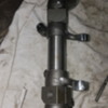
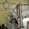
Oh, and for those of you who wonder if woodruff keys ever act like little bastards, here's a picture of how I finally persuaded the crank key to leave the loving embrace of its favorite crankshaft (after vicegrips, pb blaster, torch and gentle conversation extolling the exciting world outside of the crankshaft nose). Sometimes it just takes a slide hammer.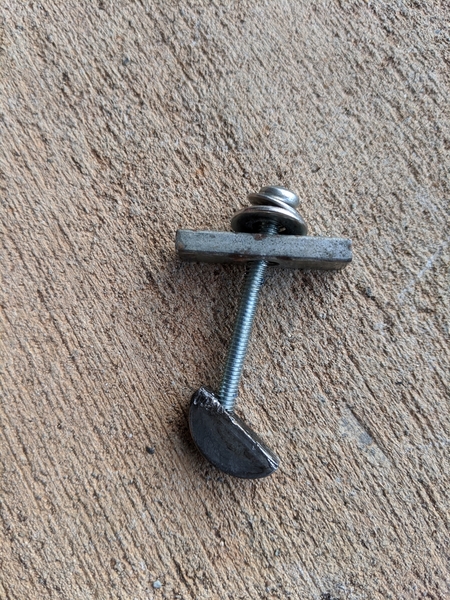
Attachments
Well, I gotta hand it to you.
You really get some weird ones.
Gordon Nichols posted:Well, I gotta hand it to you.
You really get some weird ones.
Someone must have wished an interesting life upon me. If I'm honest, I don't really mind solving problems, I just wish there was a bit more time to get bored in between.
Should be interesting to see what you find in there. The pieces are consistent with the outer rim of the slinger contacting the case within the slinger void (and also jamming the woodruff key in the crank slot), but I can't imagine why, other than there were two different washers used by VW: 51 - 60 and 61 - 79. I don't know the differences in diameter, but these guys should be able to tell you (and maybe the wrong one was used when the engine was built):
Bug City
| Phone, Fax & E-mail |
| Toll Free: 1-888-BUGCITY (1-888-284-2489) Within CT: 860-666-CITY (1-860-666-2489) Fax: 860-665-1396 Contact US |
email info:
Thanks, Gordon. Lowering the engine right now. Then a 3 hour break to tour the local bird sanctuary (Marianne decided to make me take a break :-)
Deja Vu all over again.
I originally bought a built-up 2,110 long block and finished the peripheral stuff myself. When I first started it up (after it had been sitting in my shop for two years) it ran with an ok, un-sync'ed idle, for about 15 minutes just outside of the garage and then I shut it down. 15 minutes later I wanted to move it back into the garage so I started it up, it ran for about 15 seconds and seized. I ended up pulling it down to the crank.
Turned out that whomever had built the long block skewed the #4 main bearing (next to the flywheel) during case assembly and caught the towel pins slightly off in the bearing, squeezing it tight. Used a propane torch to heat the seized bearing and it slid right off. ![]() New bearing set got installed and started over again....
New bearing set got installed and started over again....
Enjoy the birds. It'll be god to get your mind off of this for a while.
Attachments
Mike, the good news is that most probably it won't cost much but your time to take it apart and reassemble. It's just time and some gaskets and maybe a bearing set and some sealant. Maybe new pushrod tubes and seals depending on the style that you have.
Chin up, move forward, and you'll be fine.
Engine rebuild update. Good thing I have two feet cause I keep shooting myself in one of them.
After I split the case, I saw I was wrong about about the oil slinger breaking. It turns out that there WAS a washer behind the crank pulley for some reason. The pulley wasn't a sand seal as far as I could tell (had reverse threads). The slinger was intact and didn't show any wear.
The shot to the foot was a ground up brass timing gear from failing to remove the distributor drive when I plugged the distributor hole. I now am very aware of what happens. Fortunately the steel crankshaft seems to have ignored brass. The front bearing surfaces showed some light scoring so I probably caught it early.
In any event, a full set of bearings, sealant, gaskets, studs and seals are arriving this week. I also ordered. 12" long 7/32" drill to do the Hoover mods for the case.
Onward!
Always be on the lookout for those brass thingies...
Since I'm rebuilding the engine, what should I consider tweaking while I've got the case split? I'm just looking for a basic reliable power plant, but won't turn down a few extra ponies or ft/lbs if it makes sense.
Here are the basic specs culled from the ad when I bought it:
1776 cc built on a duel oil relief AJ series case
Engle 110 cam and gear
lightened and balanced connecting rods
69 mm crankshaft
90.5 mm piston and liner set
~ 8:1 compression & 52.5cc chambers
hardened lifters
042 heads
40 mm duel Kadrons
full flow oil pump (30 mm )
chrome moly head studs
case savers
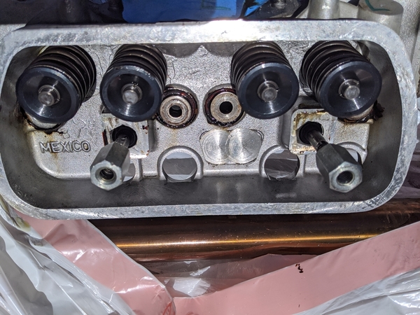
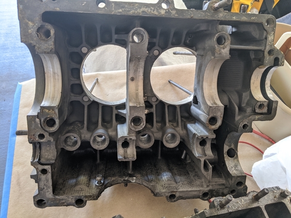
Here are engine pics that might trigger some ideas. I know @ALB will have some thoughts on this.
Many thanks,
Mike
Attachments
Easiest, cheapest thing I can think of is ratio rocker arms. Those in the photos look like 1:1
But then, you’ll need different push rods, too.
And maybe sealed, adjustable pushrod tubes.
How soon do you want to be back on the road?
Best to clean it up and put it back together nicely. You've got 85 horse in a reasonable power band with this set up. It should give peak torque at about 3500 and pull strong to 5000 or a bit more. The Kads are matched to the cam, compression, heads, etc.
What's your disty? A standard Chinese 009, right? With a Pertronix?
If so, fix that first and regardless. All the cool kids are doing it, and it reportedly makes THE difference in the parts of your power band where you will actually be operating this engine.
You buy a set of 1.25 rockers, your valve lift goes from .430 inches to .490, and effective duration is now over 300 degrees. Assuming that works with your valve springs and fits in your combustion chambers, that's great for a hotrod—but without a couple Weber 40s, some head work (ah screw it, just buy a set of Panchitos) and possibly a more deliberate exhaust system you won't get all of what you should be getting.
With the 'Chits and everything else dialed in competently you'll gain [help me out here, experts] what? Maybe 15-20 hp? If everything is assembled right you'll now peak a little above 6000 rpm and your best torque will now be around 4200. You'll lose a little grunt below 3000.
Without the heads and carbs ($1500 and shipping?) the rockers might net you 5hp at 5200 but they will still move your torque band up and away from where normal humans typically operate internal combustion engines on public roads AND require a bunch of fettling to make it run as well as it would have in the lower mid range without the changes.
edsnova posted:(ah screw it, just buy a set of Panchitos)
^ That. Then put the 1.25s on it, buy a "Black Box" (to you know, "save on shipping") and call it a day. There is zero downside to Panchitos on a 1776.
Next year when you want more, you can start writing checks again for a merged header and some better carbs. The heads won't be the limiter at that point.
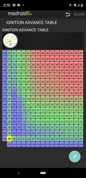
Gordon & Ed, I just measured the rockers and they are 1.25 ratio (35 mm and 28 mm centers perpendicular to center of shaft). I'm going to stay with them since the difference with this lower performance setup is probably a torque/hp wash in terms of the buttometer. The ignition system is a Speeduino ECU driving a 2000 Golf 2.0L ignition module in a wasted spark setup. The ignition curve is basically what I derived for my old 3.3L turbo engine proportionally mapped to the idle and top end advance that seemed to work for the 1776. I currently run 10* at idle and top out at 40* without any detonation. It's running rich so I may need to drop advance a little if I change jets, but that's not high on the priority list right now. If any tuning junkies have a suggestion on the spark map let me know.
Thanks!
Attachments
Screw it. Just put it together as-is and drive the guava out of it.
Everything you do from what you have now gets expensive really fast.
Gordon Nichols posted:Screw it. Just put it together as-is and drive the guava out of it.
Everything you do from what you have now gets expensive really fast.
Panchitos are $610 for a set of 2. I'm going out on a limb here and suggesting that in this day of $6500 5-speeds, $610 does not qualify as expensive.
Again: zero downside.
I suspect I'd have to catch Marianne really full of "Christmas spirits" to get a sign-off right now on $800 worth of Panchitos (cause you know I'd need just a little bit more compression plus shipping costs if I went that way). Maybe after that nice cruise we've got planned next year to Norway, Sweden, Russia, Germany and Estonia...
Gordon, sounds like a good plan. I'll just clean it up and drive the guava out of it for a while, unless my oil slinger gets temperamental again :-)
Mike, under WOT, you should be around 28-32 degrees advance up to about 4800, then retard the advance(under WOT only) 4 degrees per 1000 rpm above 4800. I would also go from 10 up to 30 gradually on WOT from 1000 rpm up to 4800.
The retard advance over 4800 was a gift from Jake Raby to me. It works superbly, you don't need high advance way up there.....
Under light load, I'm up to about 36 degrees with light load at 3000 and up.
Otherwise your curve is nice. I have tweaked mine continuously for ten years and am on version 40......
Personally, I'd up compression to 9:1, at LEAST 8.5:1. Panchitos would be great on this motor, but it's not my money. I like JayCee no-leak pushrod tubes and white silicon seals.
I want to know more about the retard @DannyP. Without a dyno, I'm just guessing (and trying to feel it: was that faster?) out here in flyover country.
Hi Mike- As you well know, any changes are going to cost money. Let's start with the easy ones-
First- as has already been mentioned, for an easy power increase throughout the rpm range, raise the compression. At 8:1 with 52.5 cc combustion chambers the engine must have up around .060" deck height. While those numbers work, a .015 or .020" drop in deck will up the compression to 8.5:1, make the engine more efficient, and may even run a little cooler. The increase in power won't be earth shattering, but will be felt from idle on up and be good for mileage as well. That engine also needs a set of solid bolt together (no spring washers or circlips) rocker shafts- it's only a matter of time before a washer or circlip breaks, and that could spell disaster! And at that valve lift (.430"?) some elephant's foot adjusters would be easier on the valve train.
I would NOT put Panchito heads on a 1776 that doesn't make power above 6,000 rpm. The small gain you'll get in the top rpm's doesn't justify the loss of airspeed (and fuel dropping out of the mix) through the intake ports the engine will experience in the lower part of the powerband. This loss will translate into an ever so slightly soggier bottom end/ low midrange (where we do 95 or 97% of our driving), which you may or may not even really feel, but the resulting (albeit probably small) mileage loss will tell you the combo isn't optimal.
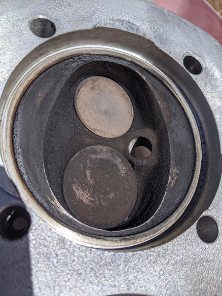
The heads look like they have stock combustion chambers with shrouded valves and no port work- how do the intake manifolds line up with the intake gasket holes? If you are looking for more power (and to spend a little more money), a set of properly ported 35 (or even better 37) x 32 mm heads would be a better choice. Ported 35x32 heads will support 120 hp (and I imagine another 5- 7? hp with the slightly bigger intake valves) and will retain all the drivability stock heads deliver. At this point flycutting the heads to 50 cc combustion chambers will give 8.9:1 (.040" deck) and still run on 91 ron (premium) gas. As Gordon mentioned, those look like 1.1:1 rockers- on 1.25's usually the pushrod cups are drilled noticeably closer to the inside edge of the face, but hey, we could be wrong (ask my lovely wife- she'll tell you it's not the first time!). VW 1.1:1 rockers have 2 raised lines on the forging. With a 1½" exhaust and 1.25 rockers (which will add 4-5° to the dur @ .050") the engine should rev to 6,000 rpm with power. I'm told (by someone who's information I trust) Kadron manifolds with ¾ of the center divider ground out will idle as nicely as Webers/Dellortos.
Hope this helps. Al
@Stan Galat- retarding the timing for better power above 5,000 rpm is an old drag racer's trick.
PS- Do the Hoover mods- you'll be glad you did!
@DannyP thanks for the spark table info. I'll definitely be adopting your suggestions. @ALB spot on ideas. I appreciate all of your help very much!
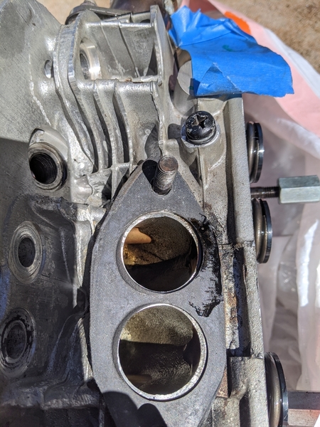
I can do port matching on the manifolds and heads if you think it's worth the time. Right now the intakes manifold openings are slightly larger than the manifold outlets (theoretically reducing the backflow). Gaskets are cut to be out of the way. I've already modified the Kadron manifolds to open them up to about an inch from the bottom. Seemed to be idling fine before I dropped the engine.
I'll measure the rocker lift ratio directly tomorrow to see if I screwed up the arm length measurements. I'll raise one side an inch and see how far the other side moves.
Rookie question, when heads are designated as "042" or "044" what does that mean? I can see that it doesn't directly correlate to valve size. I'm sure it's obvious but I've not been able to figure it out.
Thanks!
Mike
mppickett posted:I just measured the rockers and they are 1.25 ratio (35 mm and 28 mm centers perpendicular to center of shaft). The ignition system is a Speeduino ECU driving a 2000 Golf 2.0L ignition module in a wasted spark setup...
Well alrighty then! I hereby retract everything in my post after the first sentence.
ALB posted:
I would NOT put Panchito heads on a 1776 that doesn't make power above 6,000 rpm. The small gain you'll get in the top rpm's doesn't justify the loss of airspeed (and fuel dropping out of the mix) through the intake ports the engine will experience in the lower part of the powerband. This loss will translate into an ever so slightly soggier bottom end/ low midrange (where we do 95 or 97% of our driving), which you may or may not even really feel, but the resulting (albeit probably small) mileage loss will tell you the combo isn't optimal.
On the contrary: the Panchos are designed to make more air speed through the intake ports. That's their whole schtick: you get high flow numbers at high RPM and, unlike a BugPack 044 or similar, high velocity at the low end so you don't lose low and midrange torque.
Not saying it makes sense to upgrade this engine at this time but the Panchos, if they perform as advertised, would not cause a soggy bottom. Quite to the contrary.
As for what you have now... I don't know, and Shoptalk forums are probably even less expert than us knuckleheads, but here's one guy's post on that subject.
This is the MFG page for what you have.
ALB posted:I would NOT put Panchito heads on a 1776 that doesn't make power above 6,000 rpm. The small gain you'll get in the top rpm's doesn't justify the loss of airspeed (and fuel dropping out of the mix) through the intake ports the engine will experience in the lower part of the powerband.
edsnova posted:On the contrary: the Panchos are designed to make more air speed through the intake ports. That's their whole schtick: you get high flow numbers at high RPM and, unlike a BugPack 044 or similar, high velocity at the low end so you don't lose low and midrange torque.
I agree completely with Ed, and have finally found a point of disagreement with Al. One gives up nothing (as compared to a stock head) with a set of Panchitos.
A VW Mexico 043 head has 57cc of intake runner volume. A CB Panchito has 54cc. There is no "loss of airspeed" with a Pancito head. Port velocity is as good or better than a stock head, and yet it will flow 167 cfm at .500 lift. A Panchito head will outflow an "as cast" 043 at every lift from .100 to .600, often by a factor of 2x, with a smaller intake runner. At the risk of sounding like a fanboy, these heads are the best thing to hit the VW market in at least 20 years (maybe ever). Pat Downs deserves a place of prominence in the VW pantheon, and should be knighted or something.
There is zero downside to Panchitos. Zero.
Also, regarding the heads Mike's got: regardless of what the ad says they are, I'm almost 100% sure they aren't Mofoco 042s. The Mofoco castings have always been domestic (Manitowoc, WI), and the heads in Mike's first picture were Mexican castings. I'd bet a donut they are 043s.
@Michael Pickett: perhaps the best place I can direct you to compare heads, both OE VW and everything readily available on the aftermarket would be this page on TheSamba. A guy with the handle of "AlteWagen" has done a lot of work to keep it up to date.
The thumbnail is:
- OE Mexican or Brazilian VW dual-port heads are 040, 041, or 043 castings
- Mofoco heads are 042
- CB calls all of their street heads 044s, but they have 2 different castings: 044 Pancitos and everything else.
- RevMaster castings are 049s.
- AA Performance has a couple of castings from China: 500s and 501s.
Tims, DRD, Headflow Masters, and everybody else take one of these raw castings and ports to their own specs and desires. CB and Mofoco have in-house CNC porting that creates different classes of heads on these same castings for different applications.
CB also makes a giant head (Comp Eliminators), as do AutoCraft and Pauter (I believe), but these heads are strictly for high-end 1/4 mile drag motors, as the port volume is enormous. There are a couple of guys in Northern Europe carving very interesting heads from chunks of solid billet, but as you would suspect- they cost many thousands of dollars.
The power is in the heads. It always has been, and always will be. An investment in heads when the engine is torn down will pay dividends down the road when a guy wants to upgrade, because (if chosen correctly) the right heads will fit the application now and when there is more potential (bigger carbs and a better exhaust).
Stan Galat posted:I want to know more about the retard @DannyP. Without a dyno, I'm just guessing (and trying to feel it: was that faster?) out here in flyover country.
No dyno info Stan, sorry. The motor did seem more eager to rev when I did that change. Originally I had an 009, and then switched to the Megajolt crankfire. Initially I had duplicated the 009 curve, and went from there with idle advance changes, added a load curve via throttle position sensor, and the retard above 4800.
A few years later I added a temp sender tied into a global advance adjustment that bumped timing when cold, at low load low rpm only to help with idle. Love the features of the Megajolt software.
All the changes made a smoother, more eager response. That's all I've got.
Al may be sniffing too much paint, I don't know. I agree with Stan and Ed, Panchitos on any motor less than 2.0 liters is a very good thing. Above 2.0 liters I'd get something bigger, IMHO they've got too small valves. Pay very careful attention to deck height, dynamic compression, and chamber size to arrive at the correct CR for max power. Tighter deck height engines can actually run cooler than large deck height low compression motors. Don't leave any performance on the table, as a cooler engine will last longer......
No problem, @DannyP - the retard gives me a whole 'nuther direction to tinker with.
There's a Stuska dyno set up for VW air-cooled engines for sale in the Pacific NW. It's $4K, obo. I can't tell you how much I'd love to have it.
I'd share it with you if we could retire in the same vicinity.....
I am hoping to have some good news to share here in a couple weeks. Don't bother guessing boys and girls, you'll find out soon enough.
“I'd share it with you if we could retire in the same vicinity.....”
We can make that happen, guys. I really think we should discuss.
I've enjoyed retiring in Maui if that's helpful...
Stan, I'm inclined to agree that I've got 043 heads. Based on the chart you linked, it looks like the only Mexican casting was the 043. Someone took the time to machine off additional identifiers so they may have been lightly touched up. Great info!
edsnova posted:mppickett posted:I just measured the rockers and they are 1.25 ratio (35 mm and 28 mm centers perpendicular to center of shaft). The ignition system is a Speeduino ECU driving a 2000 Golf 2.0L ignition module in a wasted spark setup...
Well alrighty then! I hereby retract everything in my post after the first sentence.
Ed, based on Al's info about the 1.1:1 rockers having the two lines and additional measurements I did this morning, I withdraw my speculation that they are 1.25:1.
Looks like a lightly tuned 1776 with 043 heads. Good enough for island puttering. I've had fire belching, tire shredding beasts and don't want the worry and expense that comes with them. Too many island visitors biking around each corner or staring at the sights to go too fast.
Thanks to all of you guys for your advice. On this Thanksgiving I am truly grateful for your guidance and encouragement!
Mike
I've started the Hoover mods to the case, lifters and rockers. If you've never read through Bob Hoover's blogs, you might want to take a look. Brilliant work and observations from a guy who converted VW type 1 engines for aircraft use in Alaska. Here's a link to the HVX "Hoover mod" oiling post: https://bobhooversblog.blogspo...007/05/hvx-mods.html
Lots of folks have taken the mods and clarified things, created video instructions, etc, but I enjoyed going to the original source and getting a feel for the guy who came up with them. He passed away from cancer in 2010 and the last 18 months worth of blog posts have updates on his fight with the disease in addition to a wide ranging set of observations on how to build engines and planes that won't kill you. An amazing guy.
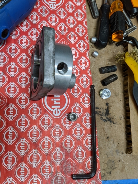
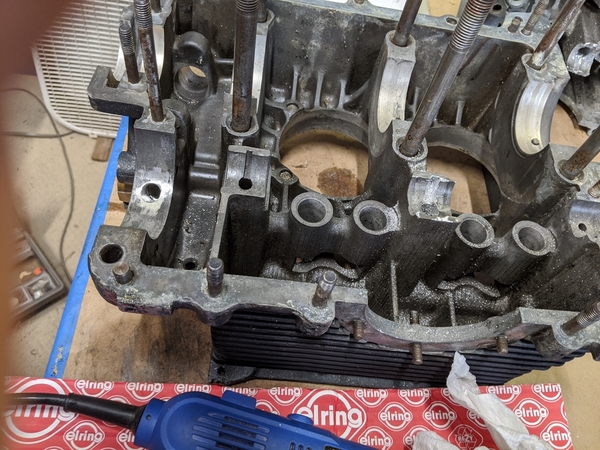
In any event, my 12" long 7/32" drill bit arrived and I slowly and carefully extended the right side cam oil gallery and then did the treacherous plunge drill down to intersect the new gallery extension without breaching either the internal or external case walls (phew!). Not hard at all, just a little nerve racking. One absolute key is to go slow and frequently pull the drill back to clear the magnesium dust and chips so they don't think about igniting. I did not use any cooling liquid, I just was very patient. The bonus was a big pile of magnesium dust and chips that made a serious fire display when ignited outside with a propane torch.
Next I'll be finishing up the various case, lifters and rocker arm tweeks that allow the new oil gallery to cool and lube the right head adequately. Then drilling and taping for the replacement NPT gallery plugs and a thorough cleaning of the oil galleries and other engine parts before the final air blow out and securing the new gallery plugs. There's a great link for gallery plug steps and comments on the #4 bearing restriction plug question (many different opinions on how to handle this plug that restricts the amount of oil that gets to the #4 bearing in an attempt to prevent oil leakage from the front pulley as the bearing wears). I'm inclined to drill a 3mm hole in a plug to limit the oil flow even though the #4 bearing itself has only a 2mm hole. @ALB, I saw you commenting on this 15 years ago on samba or shoptalkforums, any thoughts these days? Also any thoughts about best approach for rockers and rocker shafts mods to take advantage of the new oil flow?
Here the gallery plug link I thought brought a lot of info together: https://www.shoptalkforums.com...hp?f=34&t=132558
You'll see a little discussion about whether Bugpack or EMPI plug kits are better. I think this is now moot since the Bugpack plugs are also now EMPI labeled and appear to come in the same sizes. General wisdom seems to favor aluminum plugs secured with Loktite blue.
Mike
"The bonus was a big pile of magnesium dust and chips that made a serious fire display when ignited outside with a propane torch."
It's awesome stuff, isn't it? And a seriously white flame, too.
Sounds like stuff "Five Cent Racing" does. ![]()
Sounds like a grade 9 experiment Mike.
You must have read for hours before you got comfortable that you had all the info to do that procedure. Good for you. Alb will love you making all those holes to make your engine lighter. ![]()
Gordon...Most years when I'm in Mexico for New Years I toss a trans or eng case in our big fire on the beach. Once it ignites it will be like daylight for about 5 minutes ! You cannot look directly at it. In the morning when we go down to clean up the beach I pick up all the studs and reverse idler gear. Any steel parts will be the only thing left...Bruce
We sometimes throw an engine case into the fire on our summer dune buggy/4 wheel trips and it's always best to watch the reaction of someone who's never seen magnesium burn before, and then have them throw a little water on the fire...
You guys are really weird, you know that?
I mean, Really! ![]()
THIS is what happens with Magnesium chips/filings when ignited.
It is wicked hot (over 1,200ºF)
Adding water to the mix causes the water to separate into Oxygen (pretty flammable) and Hydrogen (wicked flammable). Keep watching to see the TRAINED FIRE FIGHTER shoot the flame with water, not somebody who says, "Hey! Hold my beer and watch THIS!"
And you guys are still weird.........
Here's some more wing-nut stuff to play with. A couple years ago I built a 6" tapered tube about 3 ft. long, installed a centered nozzle in it and an igniter from a propane grill. Hooked this up to a propane tank with 12V solenoid valve. Set it up on the beach and pulled the trigger. Got (approx) a 10ft flame plume. I wanted 60ft high plumes but with the valve restrictions in the propane tank and 1/4" pipe fittings on the solenoid. I was disappointed. Next time I modified a 5 Gal. propane tank with a 3/4" pipe outlet and a 3/4" solenoid valve. I fill this tank from a std propane tank each time I "fire" the apparatus. With this I get a 60 ft vertical fire plume ! Scary as hell at night on the beach ! After two firings, everything ice's up and have to wait about an hour to fire it again. I'm about 50 ft. away from the apparatus with hard wired remote control of the ingniter and solenoid. It's good for 6 firing's until the propane pressure gets too low.
I may build one that runs on compressed air and gasoline. more simple, cheaper to operate and won't ice up. I'll start by making a carburetor style Venturi to pull the gas out of a remote tank.
I don't know if this is of any use to anyone but something I always do to avoid getting gasoline IN or ON me when trying to siphon gasoline is this. If you have a pretty good supply of compressed air you can do this to start the siphon action. Put the siphon hose into the tank. At the other end (which you want lower than the gasoline level in the tank). Hold the air nozzle at a 90 degree (or slightly less) to the end of the hose and blow air across the tip of the hose. This creates a Venturi effect and vacuum in the siphon hose and will pull the gasoline up and down the hose to start the siphon action. I have found that if I have to use a larger hose, I cut the tip to get a diagonal shape. Blow the air from your nozzle against the side of the hose that is the highest. This is a rudimentary venturi shape..................How's that for some nuts info ??..........Bruce
@aircooled Bruce, 60ft high flame towers and magnesium bonfires. These hijinks are a small part of why I'm proud to consider this "wierd" crowd to be my friends. :-)
A old guy guy in my town was a "Rock Breaker". It said so on his Business card: "Arthur Harris - Rock Breaker". I believe he was also a Navy Construction Battalion Veteran who liked to build things.
He had a torch that he built that included a round, 5-gallon tank built onto a dolly, with a pump in the tank that looked similar to a bicycle pump, a pressure gauge, a sealing filler cap and an outlet connection with a 15' hose. The torch sounded similar to what Bruce built, but it had a steel fuel line going towards the front, did a 180º turn-around, then made into a 3"-4" diameter coil about 8" - 10" long going back towards the base, did another 180º and then had an end that looked a lot like an oil burner fuel nozzle. The nozzle was aimed so that the flame went right out through the middle of the fuel line coil to pre-heat the fuel and add a little fuel pressure.
Fill the tank 1/2-3/4 full of Kerosene and pump it up to 15-20 pounds of pressure, turn on the valve and light the thing. It would give a big "POP" and a pitiful flame (2 - 3 feet) and a little whoosh until that coil up front got hot and then the tip pressure increased one hell of a lot and the flame would grow to 6' - 10' long and sound like a Sabre Jet. It was pretty hot and went Orangy-Blue when it was really cooking.
He then had a tripod stand to hold the torch end and aim it at a rock....Say, the size of a Prius or so. He would get the rock warm enough in one area to show the stress fissures and re-aim the torch right at a fissure, pump it up a few more pumps to get a flame ball about 4' in diameter and then sit back, smoke his pipe and read the newspaper, occasionally give it a pump or two.
Every once in a while (you can't rush this stuff) he would pick up a 5 pound hammer and walk over to the rock, look at the fissures and, if it was ready, give it a good rap at the end of a fissure and, more often than not, a huge chunk of the rock would break off. He would re-position the torch head and repeat. Breaking up a rock the size of a Prius took less than an hour. I think it also gave him a nice, tan, too. He said that the granite rocks would hold their heat for a day or so after his visit.
That's what they did before inventing pile-driver rock crushers, I guess.
I had such a sheltered youth.
A big deal was holding marshmallows in the fire until they got all gooey.
You guys are going to poke your eye out.
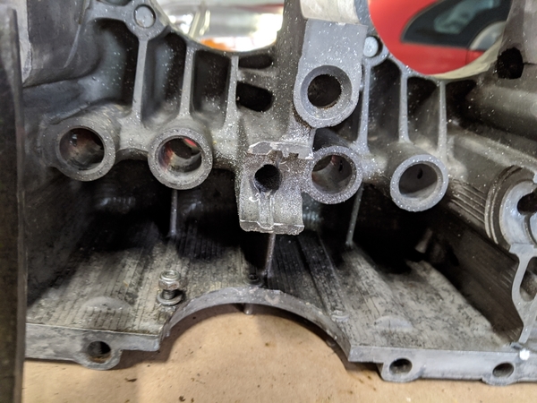
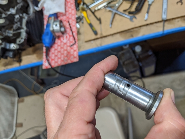
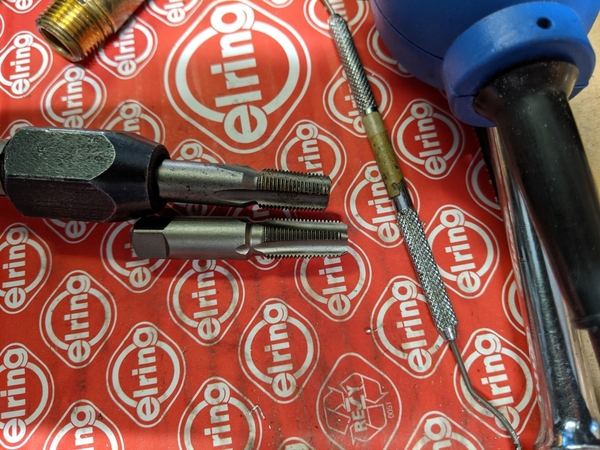
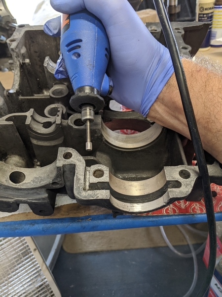
Gradual progress on the Hoover oiling and cooling mods. All of the engine plugs have been pulled and holes tapped for reassembly. I completed the case mods by enlarging the oil return passage from the oil slinger, enlarging the oil grooves under some of the cam bearings, creating 3 oil passages between the two grooves on each of the lifters, tapping and plugging the original oil pump inlet and the matching passage in the case and matching the main bearing oil passages with the case. If anyone is interested, I can do a step-by-step with pictures. Otherwise, I'll just post a few shots and the best links to review.
Next to do is grinding oil grooves under the rocker shafts and grooves inside each of the rocker arms. The extra oil (Bob Hoover said approximately 8x the original amount to the right head) goes around the shafts and into holes in the swivel feet where it then sprays onto the back of those pesky 1-2 valves. Hoover mentioned Ford and Subie oil carrying swivel feet adjusters, but I found that CB Performance carries a set for their heads and rocker setups so I just ordered from them. And everyone, I did check one last time to see if Pachittos came with the rocker setups included, they don't. Oh, well.
After hearing about flame thrower and magnesium bonfires I've just been dumping my case shavings into the trash can. Sounds like some of you guys have been hanging around Burning Man!
Mike
Attachments
Mike maybe is you did, Theron would include it in the members profile for future reference.
Just saying.
Yeah, not everyone on here (or even on theShop Talk and Samba forums) will be pulling their engine to do this, but for those who want to, a tutorial is certainly lacking and would be really helpful.
Really nice work, by the way.
A tutorial would be very very cool.
Start a new thread under the Knowledge Base/Articles.
This is an awesome site! I wouldn't even turn my computer on if it wasn't for this site.
Well, that might be pushing it a touch, but you get my drift.
mppickett posted:I've started the Hoover mods to the case, lifters and rockers. If you've never read through Bob Hoover's blogs, you might want to take a look. Brilliant work and observations from a guy who converted VW type 1 engines for aircraft use in Alaska. Here's a link to the HVX "Hoover mod" oiling post: https://bobhooversblog.blogspo...007/05/hvx-mods.html
Lots of folks have taken the mods and clarified things, created video instructions, etc, but I enjoyed going to the original source and getting a feel for the guy who came up with them. He passed away from cancer in 2010 and the last 18 months worth of blog posts have updates on his fight with the disease in addition to a wide ranging set of observations on how to build engines and planes that won't kill you. An amazing guy.
In any event, my 12" long 7/32" drill bit arrived and I slowly and carefully extended the right side cam oil gallery and then did the treacherous plunge drill down to intersect the new gallery extension without breaching either the internal or external case walls (phew!). Not hard at all, just a little nerve racking. One absolute key is to go slow and frequently pull the drill back to clear the magnesium dust and chips so they don't think about igniting. I did not use any cooling liquid, I just was very patient. The bonus was a big pile of magnesium dust and chips that made a serious fire display when ignited outside with a propane torch.
Next I'll be finishing up the various case, lifters and rocker arm tweeks that allow the new oil gallery to cool and lube the right head adequately. Then drilling and taping for the replacement NPT gallery plugs and a thorough cleaning of the oil galleries and other engine parts before the final air blow out and securing the new gallery plugs. There's a great link for gallery plug steps and comments on the #4 bearing restriction plug question (many different opinions on how to handle this plug that restricts the amount of oil that gets to the #4 bearing in an attempt to prevent oil leakage from the front pulley as the bearing wears). I'm inclined to drill a 3mm hole in a plug to limit the oil flow even though the #4 bearing itself has only a 2mm hole. @ALB, I saw you commenting on this 15 years ago on samba or shoptalkforums, any thoughts these days? Also any thoughts about best approach for rockers and rocker shafts mods to take advantage of the new oil flow?
Here the gallery plug link I thought brought a lot of info together: https://www.shoptalkforums.com...hp?f=34&t=132558
You'll see a little discussion about whether Bugpack or EMPI plug kits are better. I think this is now moot since the Bugpack plugs are also now EMPI labeled and appear to come in the same sizes. General wisdom seems to favor aluminum plugs secured with Loktite blue.
Mike
Good morning Mike- I've done the oil galley extension with a 3/16" drill in a junk case; I know Bob talked about using 7/32" (or even 1/4" if the smaller size isn't available) but all the reading I've done says the 3/16" is more than enough to keep the right side rocker area continually bathed in oil. I'm not criticizing what you did- I'm not sure it really matters what size you make those passages, as long as you're feeding oil constantly to the head. I chose the smaller drill size to make the likelihood of breaking through the case less (which was still only 1/16- 1/32" thick after we drilled through to see, although filling the depression with epoxy makes it a moot point), but I've also wondered if the larger galley size would actually give more oil pressure at the rockers, with better spray patterns toward the valve stems and springs, given the number of outlets we create with these modifications? So many questions...
I worked for a short time in a friend's VW shop (winter '79/80), took apart a fair number of high mileage engines in preparation for rebuilding and more than once Don made the observation that there was always more scoring and wear on the rockers out of the right side head. The solution at the time was to polish the shafts, reverse them and as long as the bushings in those rockers weren't totally fubar, install them on the driver's side head. We talked about how there must be inadequate oiling on the 1 side, but since so many engines went 100,000 (and more) miles before needing refreshing never gave it much more thought (that would have cut into after-hours beer time, and we couldn't have that!). 25 (or so) years later, first time I read Bob's "HVX Mods" article, the light came on pretty quickly and I've been a believer ever since.
On the Samba, STF and Cal Look Lounge I have either started or participated in threads discussing the Hoover modifications and not 1 person who's done them has reported any downside (other than the danger of going through the outside of the case, which is easily fixed with a little epoxy). The drilled passageways and notching the lifters provides full time oil to both heads and the rocker detailing eliminates so much wear (and heat). People have drilled pushrods for valve spring oiling and heat removal, while others have either notched the rocker sides or drilled through the rocker bodies to the same effect. With more oil in the right side head comes more stable temps and the a/f mixture will be closer to ideal more of the time, meaning the engine will make it's best power more of the time.
This is not the first time I've said this- even stock engines will benefit from these modifications. And yeah, if you took the time to put together a how-to (with lots of pics, of course!) I'm sure it would be appreciated. I'm looking forward to hearing your observations once it's been running awhile. Al
Thanks, @ALB, I always appreciate hearing your thoughts on a topic. As you can tell, I'm not looking for big horses out of this engine and hadn't planned on splitting the case if I didn't have to. I am the kind of guy that likes to make things better (as opposed to best) while I'm doing something, hence the Hoover mods.
I do have another question for the group, having decided not to spring for Pachittos at this point, should I do any head/port work while I've got it on the bench? As a reminder, the engine sat, rebuilt, for 14 years without being turned over before I bought it. It has dual 40 Kadrons and Mexican 043 heads. I've done the Kadron manifold porting to improve idle.
Would you recommend any touching up of the heads or head ports before I put it back together? My gut says to just port match the Kadron manifolds and the heads, but I thought I'd see what folks think before I take the time to do it. I don't want to leave any easy hp on the table, but don't want to mess up low end torque either. Thanks!
Mike
Matching the manifold passages to the head ports is always a good thing, especially if there is a big difference, but I wouldn't go nuts - you're not changing anything else regarding flow through the engine that would take full advantage of port matching like a hotter cam (are you changing the rocker arms?) or more aggressive extractor so I believe that a port-matching might not gain you all that much on that engine, unless there's a huge difference between head port and intake manifold opening.
Unless you're looking for more to do with your Dremel cable-drive and mini-rasp - You seem to be pretty good with it! ![]()
If you have the time (and the inclination- which you seem to have) there is power to be gained by some port work. Have to go look at a car (the wife was hit in an accident 3? weeks ago and her Mazda CX5 won't be returning to us; she's still pretty sore from the airbag). We're trading up a couple of years- same model, but going from a 2014 to 2016. More later. Al
Good luck on the car, Al. I'm glad your wife is recovering. Sounds like it could have been bad.
Those airbags certainly pack a punch, my daughter had some pain after the airbag went off on our 2004 Acura RL when she rearranged the body work. Hope your wife recovers fully soon.
ALB posted:If you have the time (and the inclination- which you seem to have) there is power to be gained by some port work. Have to go look at a car (the wife was hit in an accident 3? weeks ago and her Mazda CX5 won't be returning to us; she's still pretty sore from the airbag). We're trading up a couple of years- same model, but going from a 2014 to 2016. More later. Al
@ALB hope the wife heals sooner rather than later. The daughter has the 2016 cx5 was and loves it. It got 2 right tire punctured due to bad road hazard and force her to change tire. The ride of the cx5 got much comfortable /all season tires.
Prayers for your wife for a quick recovery Al. My wife and I looked at the CX 5 as well but opted for the Ford Edge SLT. It felt like it had a tad more interior room.
Thanks everyone, for the thoughts and prayers. An 18 year old kid turned into her in an intersection so she came to a stop from a 30 mph or so in an instant- Beth never even got a chance to hit the brakes. The airbag did it's job, allowing her to walk away from it relatively intact (no broken face or crushed sternum/chest), although very beat up from the airbag, and being a mother and convincing the 18 yr old she was alright, it wasn't the end of the world and his mother would be happy he wasn't seriously hurt. Recovery time from the airbag injury is 4-6 weeks and she is at week 4. Coughing and sneezing in the beginning was debilitating, but now only hurts and doesn't backtrack her a day or 2 and she's much more mobile, although picking up and carrying any weight is still a little ways off.
Beth really liked the 2014 CX5 she had (a replacement for the Mazda 5 our oldest wrecked- she seems to be going through cars about every 2 years or so- you'll have to wait patiently for the next installment, as our youngest has just turned 16) so we're not complicating it with looking at anything else- moving a little newer to a 2016 and getting it in red (she settled for a silver one because it was such a clean, low mileage car) is the objective. We think we may have found THE ONE today.
@Michael Pickett- first and most important thing, Mike is to make sure the heads have a good 3 angle valve job. There are a couple of good threads on the Samba on porting stock heads- I'll have a look later. If you get to the point of unshrouding the valves you'll be adding cc's to the combustion chambers so the heads may need to be flycut to get the compression back up for maximimum benefit.
Hope this helps. Al
Thanks, Al. Give Beth our best wishes and good luck on buying the replacement. Double good luck on the 16 year old. I remember our 16 year old, our old '92 Acura and a small fender bender tale that will doubtlessly be told in my best Gordon Nichols voice at some point...
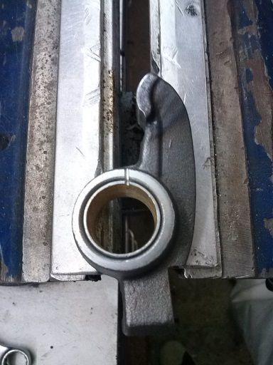
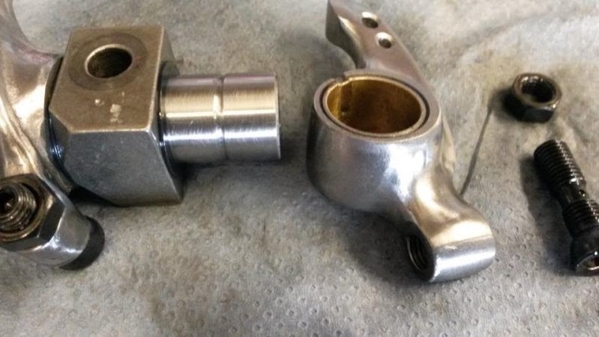
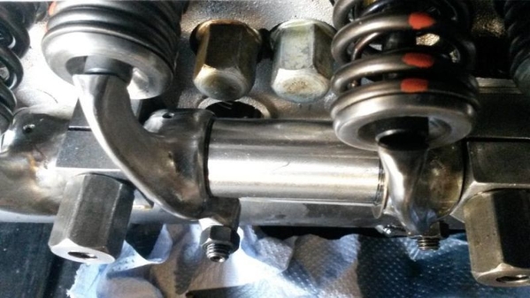
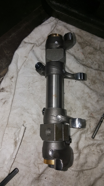
Good morning again @Michael Pickett- Hey, Mike, over the years I've saved into the computer several pics of rockers modified for better oiling and cooling the springs, so I thought I'd show some different ways people have done it. Note the notch aimed at the spring-
Another-
The 1 below was modified by a road racer; as well as the oiling tricks, he's contoured/lightened and polished them for more rpm's. I'm diggin' the holes through the area up near the pad- I don't see them really taking away any strength, but even I think that takes balls!
And then- instead of notching the side there's drilling right through the forging to aim the oil at the spring. These look like they've been reworked to be lighter as well.
and yet another way of doing it-
Attachments
Great stuff, Al. I was grooving the rockers and noticed that the two serving #1 had holes drilled through the adjuster head where it faced the spring. All the rest were normal stock. Thanks for the pics!
Mike
Attachments
Your welcome. I've also seen pushrods drilled to act as spray bars (don't have a pic) so there's a number of ways to do it.
I was checking out the validity of the so-called fully balanced engine. Over 20 grams difference on one piston/rod/wrist pin combo and a pretty good spread on the others. The crank had been dynamically balanced, but 20 grams, jeeez! After today's attention, all the pistons/rods/wrist pins are now less than a gram away from each other. The thing that took the longest was figuring out how to reliably measure the rods' small end/big end weights. Grinding and drilling was easy...
'When tires are out of balance, they often partially lose traction with the road, increasing fuel consumption. 1 oz of imbalance at 60 mph usually causes 7.73 pounds of excess force per revolution. And for every extra 7.73 pounds, a vehicle will use an equal amount of excess fuel."
NOW for engines I don't know but 20 gms is pretty close to 28.35 gms which is 1 oz.
Sure lot of shaking going on ![]() No it's Whole lot of shaking going on.
No it's Whole lot of shaking going on.
Wow! But where did you find 20 grams to grind out of a piston/rod combo?
edsnova posted:Wow! But where did you find 20 grams to grind out of a piston/rod combo?
Fortunately (?) It was spread across all of the parts with 3g coming off of the outside of the rod small end, 9g coming off of the bolt sides and the bottom of the big end, 6g drilled out of the piston crown and 2g ground out of the inside of the wrist pin. I wasn't impressed with the previous builder.
mppickett posted:I was checking out the validity of the so-called fully balanced engine. Over 20 grams difference on one piston/rod/wrist pin combo and a pretty good spread on the others. The crank had been dynamically balanced, but 20 grams, jeeez! After today's attention, all the pistons/rods/wrist pins are now less than a gram away from each other. The thing that took the longest was figuring out how to reliably measure the rods' small end/big end weights. Grinding and drilling was easy...
edsnova posted:Wow! But where did you find 20 grams to grind out of a piston/rod combo?
A production run of pistons will usually have a much greater weight variance, but are grouped so the set isn't more than 4 or 5 grams from lightest to heaviest and (again, usually) there's more than enough places on the underside to match them up. There is material purposely cast (or forged) in and left during the finish machining so there's somewhere to remove weight. I have heard of guys having to drill into the backside of the piston top to remove material, but as long as it's just a little and they are evenly spaced out opposite the 'quench pad' area of the head (so the heat and pressure of combustion isn't affecting any area of reduced thickness) they seem to survive. There's normally a little variance in the pin weight as well, and sometimes just matching the heaviest pin with the lightest piston gets everything a whole lot closer. And I know 5 grams may sound like a lot, but a piston (along with the pin, rings and clips) will weigh somewhere in the neighborhood of 450- 500+ grams so even a 5 gram difference is only 1%. If this is the only weight variance in a lower rpm production engine it will never really be a factor.
IIrc rods weigh about the same as a piston assembly (a little less? a little more? Mike, can you help me out here?) and are also made with areas for machining for those wanting to match weights exactly. Of course, it's more complicated, with there being big ends to match (so the rotating assemblies on the crankshaft are the same), small ends to match (so the forces created by the up and down movement of the pistons is the same), and overall weights to match. There is usually a bigger weight tolerance in rod sets, but with steel being roughly 2 1/2 times heavier than aluminum, there is enough excess material that normally allows a rod set to be balanced to within 1 gram (or even 1/10 gram if you so desire). It's a very time consuming process, especially if you're not set up for it. How long did it all take, Mike?
@ALB, the rods ended up at 578.5 grams each, the pistons at 381.3 grams (Mahle flat tops) and the wrist pins at 131.2 grams. It took me about 8 hours including setting up a 4x4 wood block with pins at the right heights to support the rod ends that weren't being measured. Everything got touched to bring things to an even weight. A bit obsessive, but I'm waiting on a bearing set and was left unsupervised, so what are you going to do :-)
It's not obsessive, Mike; it keeps you out of trouble and you'll be rewarded with a really smooth running engine. Since you are waiting on bearings and your rods are really heavy you could lighten them a wee bit- 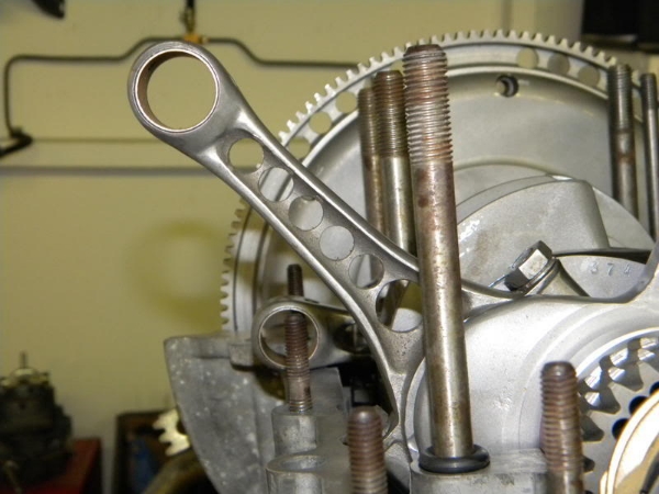
I don't know exactly how much weight was taken off (as with many others, I stole this pic off this big interweb thingy) but I think between the holes and 'shaping' it looks like a fair bit. Along with the lighter flywheel and drilled timing gear I'll bet the thing revs like there's no tomorrow!![]()
Attachments
Lightning rods!
Probably going in a Lightning Bug!
Oooh, baby!
@Michael Pickett- Good morning again, Mike. I forgot to ask earlier- do you remember how close in weight the piston pins were? I've always thought you could lighten them slightly by countersinking the insides of the ends 45°. Probably wouldn't lose much weight, but every little bit helps. You could also drill them out a short ways but leave the middle ¾ part.
When you're looking to take weight off of a car there aren't many things that give big reductions (like changing to an Odyssey battery or getting thinner glass made for the doors/side windows and molding the back window out of Lexan); you generally have to think ounces, or even grams. If, on average, you can remove 20-25% (sometimes you'll hit 30% or even a little more) of a piece's weight, to remove even just 25 lbs means working with 100 lbs of parts. That's a lot of holes to drill.
Oh, Lord, here I am rambling on again... Al
One way of making a car lighter that is often overlooked, is looking at oneself in a mirror.


