OK, folks, I've not got started yet but am noticing some things on the kit I need to ask about.

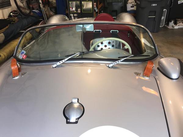
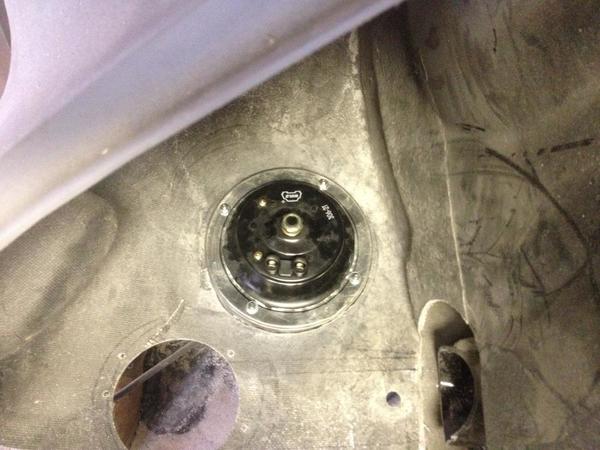
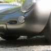
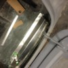
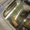
Does the TR Spyder kit come with the fuel fill hole already cut in the hood?

IMG_8267

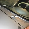
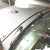
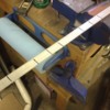
Because mine does not in any way line up with the one in the purported fuel tank. IMG_8266

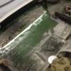
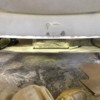
The tank is sitting in the spot it appears to have to go. It is oriented as it must be. The hole for the filler is where it has to be—the old sender hole, right?

IMG_8268

So I figure I'll have to FG over this hole in the hood and cut a new one five inches lower, which is no big deal. But before I start I want to check with everyone to make sure I'm not missing something obvious & there isn't some other, better way.

Attachments

Images (3)
  • IMG_8266
  • IMG_8268
  • IMG_8267
Original Post

Replies sorted oldest to newest

Gonna glass over the hole and cut anew. Thanks all.

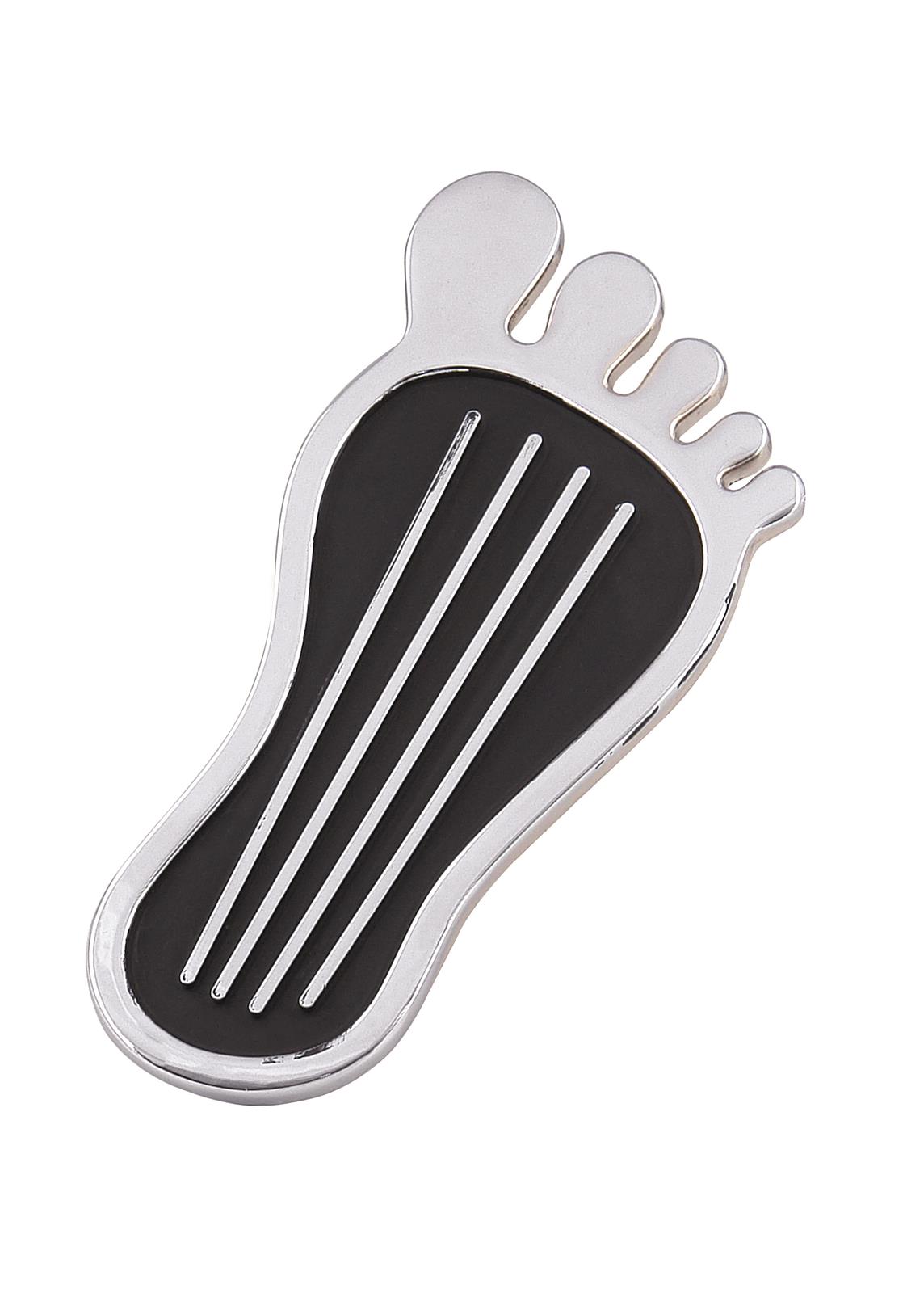
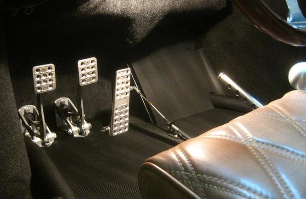
Now the next item of business: the gas pedal. I need one.

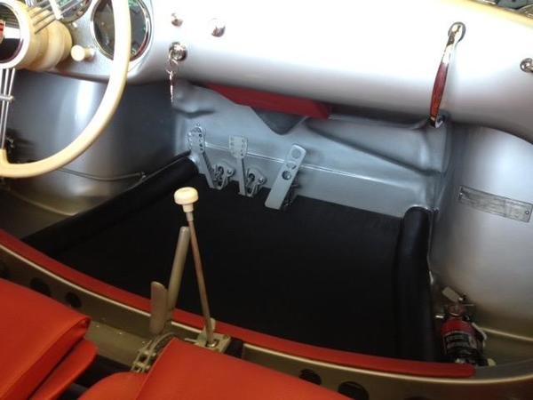
I have a clutch and a brake pedal, each with its own MC/reservoir thing. No go pedal.

The floor has a little steel L bracket with a big hole. I am told this is the standard rig. I have not yet seen just the Spyder-style gas pedal for sale. Can someone direct me to that?

Last edited by edsnova

Thanks Arajani. I was thinking the same.

It's a new gas tank. Well...10 years old but never once had any gas in it. I suppose I could have my muffler guy look at it. His guys like to weld stuff and they're pretty good at it. 

No biggie to re-glass though. I've been playing with fiberglass all winter and I have a bunch laying around.

So about that gas pedal. Seriously. No one knows what part that is? I see Fibersteel sells a very nice 3-pedal rig for like a gazillion bucks but I really only need a go pedal, as the other two look the part. A picture of someone's setup would even help. 

Ed, since I don't know jack about FG, and only understand steel a little bit, I think I'd see about a gas tank that works with the hole you have in the hood.  Authentic, and all like that. Plus might leave some room up there for something besides the tank and a bunch of frame parts.

Gas pedal? Is this just the VW arrangement sans the other two pedals?  Probably not, but if so, then these OEM sort of things are pretty cheap.  Cut off the part you dont need and rave on.  Likely not that simple.  Sorry, don't listen to me, as I don't really have a clue here. Trying to remember my old 356 lash-up.  Believe it may have been rod and socket all the way, no cable.  Now, that would be authentic, if you could manage it.  What you can trust me on here is the following:  That rod and socket contraption was a real PITA.

Very cool with the functional Jack points!

If I could do it again, I'd move the filler where yours is. You can probably get the full 8 or 10 gallons in there, plus it looks better.

Ed, I have a gas pedal. It's a Neal that is cut at an angle, painted black so you can't see the red kit-car looking Neal, and covered with an aluminum, nice looking pedal cover.

Made some more progress today on the build. Fixed a stress crack in the hood, ground and painted my frame extensions and did some other stuff.

While under the car I took a measurement from the front firewall to the beam. 6 1/4 inches, roughly.

The VW master cylinder is a bit more than 7 inches. 

I have an idea of how to make one fit, but I wonder if anyone has the solution to this already set so they can share it with me.


Pretty much. Remove the axle tube boot bolts on trans end. Use the nut on the end of the axle to pound on while pulling axle tube straight outward. Use a dead-blow.

The outer bearings are about $15-30 each, I replaced mine. Should come off with a really good smack or three. I think I slid a socket over the end of the axle and let that strike the nut.

Get a long and large pair of needle nose and grind into the ends so you can get the heavy snap-rings in the diff out to get the spade ends of the axle out. I can talk you through it if need be.

BTW, your jack points look great!

Last edited by DannyP

Thanks, Danny. I checked-in with Sartwell and he told me to just bring the whole mess and he'll install all the o-rings and gaskets on the end correctly for me after doing the new ring dear and .93 4th. I have a whole box of new parts as well: bearings, bearing covers, all the bolts, all the gaskets. So I'll just drop it all off at his shop soon enough. Fingers crossed.

IMG_9004

Now back to the horn pockets.


Attachments

Images (1)
  • IMG_9004

I had not heard of his Spyder hate.

He seems to be fine with the flipped R&Ps. When I had him do Bridget's box he was looking for an earlier case for a guy with a trike. I traded mine for a later, single side cover unit. At the time he was also finishing up a 6-cylinder Beck Spyder.

The last trans he made for me is good, and so is the one he made for Cory. The one I'm giving him to work on is already built and just needs the R&P and 4th gear changed out, so I expect he can handle it. 

Attachments

Images (1)
  • mceclip0

Trans is dropped-off at Jimmy's new shop. Lotta cools stuff there, but we were both on the move and so I didn't take pics.

914 gauges shipped to N. Hollywood Speedo for estimate. I forgot to put the note in the box telling them what I wanted, but they called as soon as they got them & we straightened it out. Those gauge jobs are like a 6 month lead time, so I'll probably set the car up with the re-pops for early sorting. The binnacle gets like a silver hammer tone finish so it shouldn't be a big deal to cut the holes later and install a plate with the new gauges in them.

Currently smoothing the inside of the rear clamshell: three skims with Fibral and a final 2 or 3 with regular filler. This is all going to be painted body color so i want it smoove, mostly, as on the originals.

IMG_9029IMG_9030IMG_9031IMG_9032

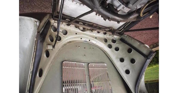
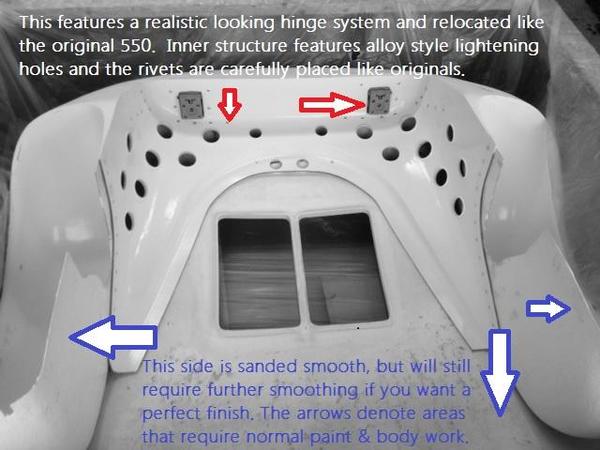
That line near the bottom is a guideline for the inner brace—that Swiss-cheese-looking bit of bent aluminum that all the original 550s had and almost none of the replicas do.

rear clam detail 3 0090rear clamshell int detail

What is most interesting to me is that the top lip of that piece is not bonded or welded to the clam itself. There's always a gap. I've already mocked it up in cardboard but I'm not quite sure yet how to make the aluminum version stay. Looks like maybe an L bracket, bonded in at the bottom of the V, held to the brace with a couple rivets...

IMG_9027

Attachments

Images (7)
  • IMG_9029
  • IMG_9030
  • IMG_9031
  • IMG_9032
  • rear clam detail 3 0090
  • rear clamshell int detail
  • IMG_9027


Well, here's one replica that has that support piece - or at least an interpretation of it:

Spyder01

Have you heard of 502 Motorworks ? These are high-end cars, made in aluminum, and supposedly homologated to race against original cars in historic events. They had one on display at Monterey.

Did I say high-end? Prices start at 'under $100,000'.


For a roller !


Spyder02Spyder03Spyder04Spyder05Spyder06


Attachments

Images (6)
  • Spyder01
  • Spyder02
  • Spyder03
  • Spyder04
  • Spyder05
  • Spyder06

Yup. Familiar with those. All aluminum, and very nice. I thought they were more like $300k.

FYI I've been away from the garage for a while and will be away this weekend too. But by way of update, I made a press mold for the rear inner aluminum and pressed the center bit as a test. It's not quite right but I think this technique will work with a bit of tweaking.

I also splurged on a set of planishing hammers and dollies, and a couple of flangers to facilitate said tweaking.

I'll post in a couple weeks when I return to it.

The guys from 502 are amazing -- really knowledgeable, very kind and extremely helpful. I know them well and have interacted with them (last a Monterey two years ago). 

The price of under $100,000 seems to be for a body and chassis (from their website). I'd imagine that, once it is painted and fully assembled, it would be in the $200-250k range. 

The most elusive aspect of the Spyder is the rear fenders. It is a tough shape to get right. Even with the variations between bucks within the Wendler plant, many of the replicas are still a bit different. 

The best I've seen is the one from Rusty Tubs. 

Anand

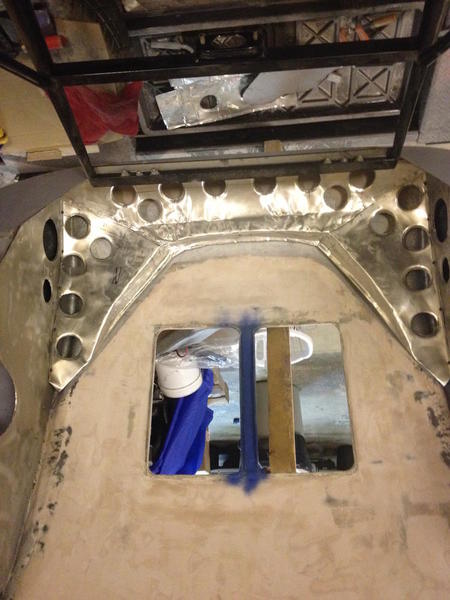
Been away from the Spyder for a couple weeks: trips to see the eclipse and then the inlaws. Today I bought a couple sheets of 22 or 24-gauge aluminum sheet to do the inner clam panel with, when final. I've bent some scrap this thick and also some flashing, which is about half as thick (and wrinkles quite a bit), working out the shapes and planning. Here's the center section from that first try with the thin metal.

IMG_9143

I think the thicker metal will look better and also be a lot stiffer. I also think I'll be able to braze it together rather than relying on rivets and body filler.

Attachments

Images (1)
  • IMG_9143

Looking good Ed. I was over Bill's place in Potomac MD last Monday his 550 is now up and running. He's done some really slick mods to add more cool air from the grills toward the engine. Basically he designed sort of a wing under his puller fan that's attached under the grills with SS sip ties. It pulls the air in then blows it on the wing which then moves it to the engine and carbs. Also built in the wing is his oil cooler which receives the fan air as well. It works really well and when kicked in without the motor running sounds like a turbo-jet. You gotta see it. Unfortunately I've got a pretty good oil leak going since my engine pull in July not sure where it's coming from but every time I drive it I'm cleaning up oil. So I have to take the engine out again what a pain.  Makes me think about doing something similar with a smaller fan under the spare wheel. I like the look of having the spare. Bill is not using his. 

Pete

Continuing. Gonna start final smoothing and paint on the inner clam this weekend (fingers crossed). Here's a selection of inner clams (all oriented similarly) for comparison purposes:

550-0090 (the one Spyder Factory, Alloy Cars, etc. all copy):clam detail1 0090 copy

Here's one from a UK-based high-end replica maker:

UK alumkit inner clam copy

from Rusty Tubs' $4,500+ fiberglass "clam correction" kit:

rustys inner clam copy

And Ed's homemade Crinkle Clam (TM):IMG_9258 copy

Attachments

Images (4)
  • clam detail1 0090 copy
  • UK alumkit inner clam copy
  • rustys inner clam copy
  • IMG_9258 copy

Danny's got a Jamar that he modded. Bought good heims and booted them.

I'm curious to know why the shifter would move more with a cable rig than a solid linkage. I hope it's not because of my linkage mods. 

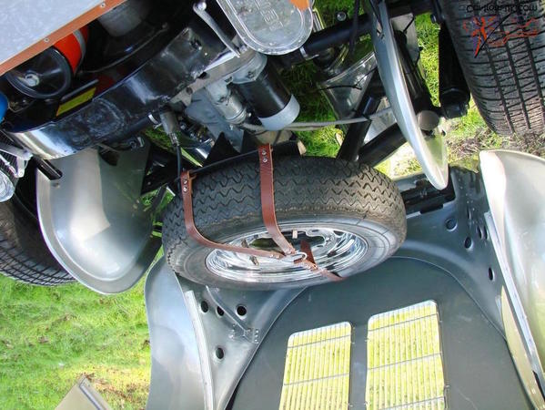
Spent six hours today on the spare tire rack. Yes, that is a bent Spyder-style tail brace, and yes, I do also plan to make Spyderesque forebraces for it, with hidden bolts so it's removable.

The shock-tower brace will also be reformatted for extra strength.

(previous identical post deleted to correct faulty link)

Attachments

Images (1)
  • mceclip0

Great job Ed! Did you happen to weigh the piece before and after the holes? 

When I was drilling the hardened gears for my trans I had to buy carbide drill bits (HSS and even cobalt would barely make a mark), which when you break a bit (2-1/8" at $22 each and 1- 1/4" at over $50) in the middle of a set up it got pretty frustrating. I can't say enough about rotary tables, though- pretty neat equipment!

I've not weighed the stuff but I'm pretty good at estimating weight, and I estimate the big tubular piece (including the through bolts) is about 6-7 pounds. I'll look around for a fish scale to weigh it. The modified cross brace is about 6-7 ounces heavier than stock, and that saddle is a few ounces. The "Swiss Cheese" inner bracing is ridiculously light. Maybe 2 pounds, 3 tops.

I estimate the whole aluminizing-and-details project will total under 50. Maybe under 40. Running Vintage 190s instead of steelies should more than make up for the extra weight. 

btw your car is awesome. I might copy the drilled wiper arms. Love the hard tonneau. 

Last edited by edsnova

I love seeing what other people are doing because I love the details, sometimes it makes me laugh at myself. For example, I built a big 3/16" thick steel structure with welded cross members to support my front bumper, it probably weighs 25lbs. then I built a steel tube frame that hung off of it to support the battery, it probably weighs 3 or 4 lbs, total 29 lbs. Then I built a 16 ga sheet metal tray for the battery, probably 1 lb. then I punched and drilled a bunch of lightening holes in the sheet metal tray, probably saved 5 grams! BUT!... it looked cool!  I think I'll add a second battery and drill out my wiper blades!

Gonna do something like you did re towing loops. You've got two bolts into the frame and your loops are (I think) about where my bolt through the frame extensions are. I think you said ground clearance on that was about 4 1/2 inches? How's it working?

I ask because my idea is to use my bolts as the rear support and the jack points as the front, with the towing loops just in front of them, maybe 2-3 inches higher off the ground (and easier to reach) than what you did. 

But before I get started I want to learn all I can about flat-towing Spyders with homemade towing rigs. And you're the only guy I know so far that's done it!

I have about 3.25" between the ground and the bottom of my tow poinst. I have bottomed out on them twice with a passenger. I do live in the mountains and the roads around here aren't exactly smooth or even. I'm OK with that.

I have yet to fabricate my tow bar. If I didn't have any plans for a tow bar, I would've made the tow/tie downs flat and had them stick out farther. I do use them as jack points though.

I did fabricate a spoiler that mounts to them, but I plowed my gravel driveway a couple of times with it, so I took it off. If I lived somewhere where I frequented highways, It might come into play, but it doesn't do any good on the twisty back roads that I drive on. I avoid 4 lane roads as much as I can.

tow pts

Attachments

Images (1)
  • tow pts

Wow! Looks great Ed.  Only thing is you're taking away some storage area up front. I carry tools, jack, convertible top, etc. in those spaces. I like the extra room ahead of each front wheel and think it's good to have the lbs up front to hold the front down some during high speed.

Keep up the great work, gotta get my butt up to see your build in progress in person though. Bill from Potomac MD is swapping out his transmission for one that can better handle his engine he just built for his 550.

I spent some time making a LeMans red beehive pit crew light for my car and installing LeMans French roundel stickers as in the period pictures of LeMans racing 550's.  I didn't want to drill any holes in the car so like my rear deck mushroom marker light and right side marker light I used and LED with a watch battery and micro switch to turn on and off.  I used a Heineken aluminum beer can top as the base the plastic beehive fit it perfect on top and I had a beer! This was then UHU glued to the can top, I cut a slot into the beehive for the micro switch and press fit it with CA glue, wired it up to a 3 volt watch battery it works great and looks the part. Most folks won't know what it was for. My understanding is at night when racing at LeMans it was used to signal the pit's they were coming in. No radio coms back in 1955. IMG_0890IMG_0892IMG_0908IMG_0910IMG_0912IMG_0913IMG_0914

The back except around the battery was filled with a two part epoxy with enough room for the double sided 3M tape to stick it on the car. This 3M tape works great and you can get it off with some lighter fluid if needed.

Pete2017-03-13 17.35.282017-05-02 18.52.45IMG_0935

Attachments

Images (10)
  • IMG_0890
  • IMG_0892
  • IMG_0908
  • IMG_0910
  • IMG_0912
  • IMG_0913
  • IMG_0914
  • 2017-03-13 17.35.28
  • 2017-05-02 18.52.45
  • IMG_0935
Last edited by mtflyr

Still cutting up this s.o.b...

IMG_9852

Question for other Spyder guys, particularly Beck owners: does your car have a steel square tube running inside the cockpit bulkhead (directly below the dash)? Those rivets in the picture attach the fg to that steel. I did not drill the smaller holes in the fg so as to avoid messing with that steel. Any knowledge and/or advice much appreciated.


Attachments

Images (1)
  • IMG_9852

ED,

Yes, my SE/Beck does. You can see it carpet covered in one of the attached pic's. When I replaced my clutch cable and throttle cable and rubber fuel line this Summer to make it easy to do, I used a hole saw and cut an access hole in the top. Suggest you think about doing the same without it it's a challenge to attach a new clutch cable and throttle cable feed.

Mine also has a shallow U shaped steel channel from the fire wall to the dash area FG brace. It holds the fuel line, e-brake lines, one hard brake fluid line and steel clutch cable tube. You can see this channel and what's in it. The cable shifter tubes are routed I think about half way from the shifter exiting from the channel under each seat you can see those too. This entire channel has easy acces you just have to remove the Velcro leather. 

I changed the clutch cable through the std VW type access hole in my SE/Beck Speedster and it took a lot of contorting and time.  I didn't want to ever have to do that in the Spyder or the Speedster again without better access. Having an access hole in the Spyder should make this job pretty easy to do on the road in an emergency (I carry a spare of each cable in each car). Pete

IMG_0959IMG_0960IMG_0961). 

Pete

Attachments

Images (3)
  • IMG_0959
  • IMG_0960
  • IMG_0961
Last edited by mtflyr

Thanks, Pete. I figured it was standard-issue.

Just so we're clear though, I'm talking about what's under the latitudinal bit that's right in front of the shifter (as in your second pic, above). It's not covered by carpet; it's hidden by the rounded fiberglass bulkhead that you stick your legs over to reach the pedals. It ties the 3-inch round frame tubes together with that flat bit of steel that runs down the middle of the floor.

Mine has four small holes drilled through it to run cables, brake and clutch lines (you can just make them out in the pic). I had assumed that running those through would be relatively straightforward. I'd very much like to hear the details about why it is not.

My question is cosmetic: does anyone drill the typical "lightening holes" through the fiberglass part and if so, how to do it without compromising the brace, and how's it look afterwards?

My tendency here is to leave it as-is. I like the look of the holes, and the car I'm copying has them, but—despite all evidence—there are limits to my fanaticism in this regard.

Well, it was slow going until this afternoon. Suddenly, in three hours, I got both front fenders wells, side tub walls, front floor bits fitted. I was working so smoove I only took like three pictures, none worth sharing.

The plan now is to get the rest of the tub parts done—the floors under the seats, the box sections ahead of the bulkhead (with the last oval hole), the (inside) firewall and insides of the doors and maybe bond them in on Tuesday, since it's supposed to be warm. 

Then it's down to the outside firewall and underbelly, plus a bit of adjusting, and I'll be basically done with the aluminization project.

—at which time I can actually begin what we usually refer to as "assembly."

Very stoked indeed.

Not much, Alan. I've got a little electric radiator thingy in there. Doesn't do much, but so far I don't need much.

I know what I want to do: a nice gas heater up near the ceiling, vented through the existing chimney. Hopefully I'll get round to it, too. The hold-up is running the gas line out there. Needs to go through some concrete and then into a crawl space and then up through a wall. It's a bit of a project, and I have not yet got up for it. Plus: money.

Today it was 53 in there and I worked for 4 hours or so cutting and bending aluminum for the tub. Should be on schedule to lay it up over adhesive by tomorrow afternoon.IMG_9876


Attachments

Images (1)
  • IMG_9876
Last edited by edsnova

I've got a two-eared radiant propane heater for when the cold wave comes. Also a "yellow flame" can heater. My problem (if you can call it that): the garage is about 1200 square feet. Pretty well-insulated, with some drafts along the floor. I can run the propane all day and it's fine, oxygen levels-wise. But the heat doesn't get all that hot, and the ambient H20 level also climbs pretty high, so it's no good if I need to paint anything—messes with even rattle-can primer.

This could work out though, since the next phase of work should not involve much (or any) paint and little or no (I hope) fiberglass and adhesives work: Mostly rivets, screws, wiring looms, grommets, nuts, bolts, etc. 

The plan right now is to get major assembly done by late February, if possible, then take it apart and paint in March or early April, and then re-assemble by early May.

Here's hoping I surprise myself.

Last edited by edsnova

When I was building Pearl, back in the ‘90’s, one of my neighbors upgraded his forced hot air furnace to a bigger, newer one and I got his old one - an 85,000 BTU unit - for nothing....Just get it out of his yard.  It ran on oil.  Parked it in one corner of my extended, one-car bay, ran the flue through a “Powervent” and out the back wall, put a sheetmetal 90° outlet on the top to direct the hot air into the shop space and ran the fuel oil from a tank sitting just outside the back of the bay.  It could go from 20° to 70° In about 30 minutes.  I went through 300 gallons of oil in four years, running it a lot of the time at 55° just to keep tools warm-ish.  I really miss that furnace.....

Safety Jim posted:

I have often thought about “winterizing” my work shop.  I am just too cheap to pay the gas/electric//propane bill.  I am considering solar, but after deep thought, I live in Buffalo and we have only a handful of really sunny days in the 11 1/2 months of winter. ;-(   Merry Christmas.....


Our house ( bungalow ) is heated by a horizontal loop heat pump which is quite efficient and I found a run in the basement which was easily diverted into the garage. No cold air return but it doesn't seem to matter for my purpose. I'll back that up with a couple of small electric heaters to keep things around 20 C anytime for a few bucks and for any emergency heat needs I can run a propane heater like Alan described above. I'm always concerned about co2 but as I read it, if the burner is well tuned, propane exhaust won't give much to be concerned about. We also have two windows facing SW. Only the main garage (insulated) doors and the SW wall are exposed to the elements and that one wall has 6" of insulation plus 2" more for the stucco. 

Sounds like a nice set up. I have built a few (3) garage / workshops and my most recent one is in need of insulation prior to trying to heat it. 

Dont be too concerned about co2... but, watch out for the “silent killer”  carbon monoxide, CO.  You are right about propane, LP being a clean burn. However, it still produces CO. Use caution and guard with CO alarms. They are cheap!

Safety Jim posted:

Sounds like a nice set up. I have built a few (3) garage / workshops and my most recent one is in need of insulation prior to trying to heat it. 

Dont be too concerned about co2... but, watch out for the “silent killer”  carbon monoxide, CO.  You are right about propane, LP being a clean burn. However, it still produces CO. Use caution and guard with CO alarms. They are cheap!

Thanks for that, Jim. I did mean Carbon Monoxide....not dioxide. Sadly enough, I attended the funeral of a very good friend of mine many years ago up here. He, in his late 20's then...a boat builder by trade, his beautiful Wife and two toddlers all died in their sleep one night after something went wrong with the furnace exhaust after having the heating system serviced earlier that day. In that neighbourhood they would have been on propane.

Saddest thing I ever saw...two full size caskets with two little ones in between. 

but, Jim...on a lighter note....my Wife and I had a couple of drinks with Matthew Barnaby and his Wife in a club in Ottawa recently. Small world, eh ? 

Last edited by David Stroud IM Roadster D

Managed to get the floor under the dash and the wheel wells laid up yesterday. Made the box section ahead of the the driver's side bulkhead. And also made both firewall skinz. These'll be epoxied instead of glued with construction adhesive. I don't believe there'll be enough heat to matter, but the epoxy will be more righteous in case there ever is. The floors under the seats (thicker sheet) also will get epoxy.

There'll be rivets too, of course. Hope to be all done by EOD Saturday.

IMG_9885IMG_9889IMG_9891IMG_9892IMG_9893

Attachments

Images (5)
  • IMG_9885
  • IMG_9889
  • IMG_9891
  • IMG_9892
  • IMG_9893

Inside of the doors are aluminum sheet. On top of the sheet will be upholstery (I called for a barber pole sample). I have the proper door handles. The doors will of course be painted blue like the rest of the car.

The "tab" toward the front of the rocker boxes is a notion. On the originals (after about number 0025 or so) there's a curved tubular bit that roughly follows the contour of the door void. I tried bending the shape yesterday by hand and got pretty close, so I bought a length of 3/8 aluminum rod to make a buck with for the next try.

You can see the front bit of the part in this picture.

550-Spyder-dash

The tab is a possible attachment point; I can always bend it over later if needed. I know it's not "correct," as the originals' sill tops were flat, but the replicas kind of win here with the molded sill surround: I plan to run a D-shaped bit of weather stripping around the outside perimeter.

The top of the door sill will get a tapered bit of vinyl upholstery.

The aluminum will also be painted body color, and the rocker boxes will be covered in vinyl, extending down to the frame tube as pictured. I plan to attach the bottom edges with velcro so I can stash stuff in the rocker voids. 

Attachments

Images (1)
  • 550-Spyder-dash
Last edited by edsnova

Put a couple nice dents in my firewall today with my homemade rivet dolly. Ah well.

IMG_9956

We're coming in for a landing now with the aluminum bits. There's still a bunch of little tabs and corners to make, and a few more rivets to pop, but I can see the light.

Wife got me a bead roller for Christmas so I'm going to have to resist the urge to roll a bunch of half-rounds and rivet them on in random places.

IMG_9953

I did, however, put this one in...under the torsion bar housing where no one will ever see it again. (The bead hides the backs of those big rivets down near the floor).

IMG_9954


Attachments

Images (3)
  • IMG_9956
  • IMG_9953
  • IMG_9954

Bead-rolls do exactly that! It's an entry-level "bench-top" thing (Woodward Fab’s WFBR6) but still a very cool tool—can't wait to really get into it. The flanger dies alone are probably going to be worth their weight in gold. I haven't even got them out of the plastic yet.

There are only a couple of spots on the Spyder body that had the rolled panels: under the dash, inside the front firewall (a V-shaped bit); and curving around the inside front sides of the rear fenders (on later cars; early ones mostly had a kind of Jetson's-style wedge reinforcement).

I got the thing because I want to make a 547-style fan shroud and I don't see how it's possible to radius the front and back edges correctly with just my caveman-style plywood press and/or croquet-ball-hit-with-a-rubber-mallet methodologies. There are dies to put a rounded edge on things while leaving the rest of the panel flat. That looks like the ticket.

I'll probably do a whole new thread here when I get into the fan shroud project.

Happy New Year everyone.

Bead Rollers are way cool.  I have one, haven't used it in decades but they are fabulous in the right instances.

For those panel dings in Aluminum, do you have a set of these:?

https://www.walmart.com/ip/7-P...mp;wl13=&veh=sem

The hand anvil, plus a soft-ish nylon or hard rubber hammer and then the sandpaper and buffing should do it.  Don't go nuts or it will thin out on you.

Yes, Gordon. I bought that exact kit a few months ago and, as it happens, the comma dolly is what made those marks!

(I drilled a divot into one side to cup (and not deform so much) those big round rivet heads whilst I smashed the other ends of them with the planishing hammer. Then I held it too tight and too flat against my formerly clean aluminum skin, resulting in those mars). 

The other "real" rivets I have for this project are much smaller and flat-headed—both more like what the original Spyders actually had AND easier to set without a proper rivet tool. I won't need to do too many more. I think.

Been a hard couple weeks: deep freeze has prevented my spending any time in the garage. 

I did order five yards of "barber pole" vinyl, plus a set of seat heaters, and got in touch with my upholstery guy to make sure he's still in business. (He is).

Bought another sheet of aluminum, and ordered a set of spoiler dies. And I spoke at to Bic Green, who has designed and is almost ready (has been almost ready for a couple years tho) to ship a pretty neat looking 547-style fan shroud for Type 1 cars. He says it should be rolling into production by summer's end. Too late for me (I think) but it was sobering to get his insight on what it takes to make the design work. 

As with all things: harder than I suspected.

I may still try to make one but pretty sure this car is going to roll with the existing Raby DTM shroud and Type 4 integrated oil cooler.

That of course would make my whole front oil-cooler ducting system redundant, and obviate the need for the high volume oil pump I already bought.

Making things neater and simpler goes against my nature (in particular when it also makes them less "hey-that-looks-just-like-a-real-Spyder"), so I'm kind of stewing about all this...

Mainly, though, just itching to get back into this project.

Tomorrow is supposed to be over 40F. So with luck I'll be able to get something done.


Decided to take a break from finishing the interior aluminum and instead tackle the Autopulse manifolds.

Here's the look we're shooting for:

—minus the weeping fuel, of course; mine will be strictly fake.

A little electrical conduit, a bit of aluminum tube, a little drilling and some cutting, and I think they're shaping up OK:

Got a little brazing and some epoxy to do, and I'm gonna source some bolts or studs that will screw into the fuel pump inlets so's I can affix these.

Then it's down to a couple plugs, cleanup and paint, making a couple simple brackets, and hanging them in the car.

Attachments

Images (5)
  • mceclip0
  • mceclip1
  • mceclip2
  • mceclip3
  • mceclip4

Just so everyone knows, these Autopulse manifolds are unobtainium. One of the Spyder guys—Aussie, I think—had a batch cast a few years ago and sold them out instantly at $300 per set. Not including the correct, skinny banjo bolts which he said were another $300 a set to make.

I was like...wuzzah?

Remember, the pumps themselves never work; the bellows inside are all rotted away. So it's just for looks. (These guys rebuild them...ask them how much. Sierra Madres "out of stock" at $8,803).

Anyway, if it just has to be the right shape and size, I could do that!

Made some brackets out of diamond plate I had lying around the shop, mocked the pumps up in the car. Now it's down to a little epoxy, sanding and paint. I got this. 

IMG_9996


Attachments

Images (1)
  • IMG_9996

That is a really cool replica, Ed!  And I know how hard it is to get those internal rubber parts reproduced.  I tried and abandoned that direction when confronted with up-front and reproduction costs for my heater fuel regulator.  $60 - $80 per diaphragm was out of sight for me, but not to those deep pockets out there seeking authenticity.

There is a shop in New Jersey reproducing those pumps to original drawings, but they are STILL unobtanium, as the Spyder Factory has them under an exclusive contract.  I'm not sure who's doing the cast parts (the NJ guys aren't) and suspect those come from a foundry in NH or Mass. - there are several foundries doing cast aluminum and other metal parts around here.  All of the work involved in making faithful parts to original drawings is probably why the reproduction 550s are now over a $Mil each...

"Fabricator Ed" wrote: " if you know what a working Autopulse sounds like, you’ll know that ain’t them."

Well, yeah, but you've already (wisely) bought that Carter-style rotary pump.  You could have bought a couple (1 in series for redundancy) Facet clicky-clack pumps that would have made the same clicking racket that the originals did!

Then you would need a really loud exhaust to be heard over the noise of the Facets...

You guys are hilarious but I have to admit this very humiliating fact: I actually did ponder buying some kind of 10-second timer thing and wiring that in series to the 12-volt Autopulse so when I turn the key/pull the "pump" switch the thing would make the clacky-clack noise. 

We rightly complain here all the time about shoddy Chinese knock-offs and such, but one thing this little endeavor has brought home (again) is the sheer betterness of new stuff. Each of those Autopulse 500s weighs about as much as a loaded Colt 45. And they leaked notoriously. And, at the time, these were aircraft parts

The Carter, by contrast, weighs as much as an empty water pistol, costs about the same and reportedly never leaks. You look at stuff like this and wonder how anyone managed to hotrod anything back in the day. 

Those guys were doing 180 mph down the Mulsanne driving absolute rubbish: 600-lb straight-sixes lit by Lucas electrics. Bloody drum brakes! The mind just boggles.

Auto-pulse??  WTF??  I am completely blown away by this. Unobtainium = cast aluminum -- what could be so hard? I gotta believe that you could start from scratch, and not have to spend 8,000 bucks to do it.  But what do I know??  If you have a real one, laser scan it, rapid prototype the pattern, sand casting, or whatever, pump 'em out  $20 each.  I mean, they did not spend that kind of money to make the real ones, albeit they did so for mass (1,000s?) market.  And they did not have computers.

Ed, the advice about the Disney shop is good.  I could see you running the shop in five years.

Kelly I think the $8k price is mostly in the working pumps, which are fiddly and very old. The copper(?!) bellows at the center of them are interesting. There are dozens of other parts in there too.

You're right about the manifolds though. If I were a better man I'd make wax copies of my bogus ones and then sand-cast them out of aluminum and tap them for functionality. Heck, maybe it'll even happen.

You're probably right about the pumps themselves too. There appears to be a lot of P-car pricing at work here.

Thanks, Danny. I've thought of that but finally figured the fuel pump's gotta be somewhere, and I think I've got a safe and practical design laid out. 

The plan is for steel lines down the driver's side, as original, through the rocker box and around to the firewall. The pump will be at about the lowest point in the system so it should like that—I'm told they like to "push" and not "pull." I plan to put a fuel cutoff right before the filter to facilitate changing that, and in-all it should be more accessible than the typical spot just under the tank up front, where it's easily forgotten. 

Could it leak? Sure. Would a leak there be worse than one above the beam? I don't think so. First of all, you'd notice it much sooner. 

There's to be no carpet in front of the bulkhead, and no vinyl either, so a leak there would be easy to clean.

Now, the rocker-boxed fuel line is indeed more vulnerable than a centered line in the event of a driver's side T-bone event. But in a Beck frame, such an accident would likely result in a closed-casket scenario anyway. And, even so, the fuel line would probably not rupture, given the looped rubber line over the pumps.

So that's how it's gonna be on this car.

And I'm also going to tempt fate by installing the correct glass bowl fuel/water separator in the correct spot on the firewall, since I have one and they look cool. Stan's already warned me about this folly, but I'm putting it in, and if it doesn't leak, it's staying put. 

(If it does leak, it might still stay put, albeit bypassed).


Does that hump, where the drain for the gas tank is, interfere with using the gas pedal? Mine does, that's why I have to drive shoeless on that foot.

I'd love to remove mine one day, but this is something that needs to be done at your stage of the build, not when the car's done like mine. I was thinking the removal will coincide with a custom gas tank. I can dream....

I did build a foot rest for the passenger. I made mine out of wood and covered it in some ribbed vinyl and black paint. I also made some floor mats of the vinyl. I do have plans on making one from aluminum. My original plan was to hide a small electric heater behind it, or install the heater behind the front beam and use the space behind the foot rest for hot air plumbing.

Foot rest

Attachments

Images (1)
  • Foot rest

Carlos, your pedals look great and that pic is helpful. Thanks.

Yes, I think I want to cut that scrotal intrusion out. It interferes with my feet and I'm a size 8. I don't know how any normal-sized American man could drive this type of car with that thing there.

My neighbor has had my gas tank now for going on six months. He welded a plate on top so I can put the filler neck in the right spot, but last time I asked him about it he said he wasn't done. I guess it's about time to get it back.

Hoping I can fit it in, check clearance and put a fuel outlet bung up near the front, then cut out any unneeded stalagmite.  

Then I can glass it back, and glass over my gauge holes at the same time.

Meantime it's on to the steering column. Apparently there'll be some trimming.

I might have to get out the instruction manual...

IMG_0065

Attachments

Images (1)
  • IMG_0065
Last edited by edsnova

Made some seat track supports/floor reinforcements today.

IMG_0102

These will be drilled for lightness (of course!) and welded in. The seat adjuster studs bolt through them. I made holes in the floor for socket access and I have plugs so they'll end up about flush with the bottom of the car.IMG_0104

These and the adjuster tracks will raise the seat bottoms off the floor about 1 7/8 inches. There'll be 4-5 inches of adjustment front to back, and room to shim the front or back of the seats up about 3/4 of an inch. To go lower you'll have to cut out these bars and/or lose the seat tracks.

It was interesting to note that the seats that came with the car are different sizes. One (arbitrarily I'm using it as the driver's side) is about 12 1/2 inches wide across the bottom, the other is 11. That's some serious Jet Blue-sized seating right there!

Attachments

Images (2)
  • IMG_0102
  • IMG_0104
Gordon Nichols posted:

The Webasto is about the same size (323*120*121mm&nbsp and I keep seeing them on ebay for under $400 new, but at that price, it is undoubtedly a Chinese knock-off.

Yes, Gordon, much more likely $1000 for petrol, although the ones that run on diesel can be had for about $750 pretty regularly. I personally am not buying a Russian,Turkish, or Chinese knockoff. The real deal Webasto is a quality piece, and about $500 beans cheaper than a comparable Espar. I was honestly not expecting how nice the heater is. Every part was packaged and labeled clearly, and the wiring harness is clearly German. Instructions are VERY clear and concise. And I can get replacement parts here in the USA if need be. Doubtful spare parts on knockoffs.


Carlos $840 free shipping:

 https://www.ebay.com/itm/WEBAS...0677%26rk%3D1%26rkt% 3D30%26sd%3D122808557292&_trksid=p2385738.c100677.m4598


I bought T and ducting and outlets from Espar of Michigan, and ended up around $1000 all-in.

Last edited by DannyP
Post Content
×
×
×
×
Link copied to your clipboard.
×
×