

Love the VROOM VROOM and then some VROOM VROOM
I may not have actually said, "Vroom, vroom."
But I've sat in the garage, one hand on the wheel and one on the shift knob, and seen that special stretch of county road, where it crosses the creek and goes sharp left right after, requiring a well-timed four-three downshift, with just some light toe on the brake, when the morning light was low and filtering through the trees, and the air just cool enough that the motor was nearly as happy as I was.
Nicely written, Mitch.
Spent five hours today fabricating more details, though these may well alleviate a common problem with replicas. Anand will know what these are going to be. Anyone else?

Attachments
Images (1)
edsnova posted:...these may well alleviate a common problem with replicas...
Ah, those must be lightly galvanized soft steel rusting pucks, sometimes bolted to the inner rocker panels of fiberglass-bodied cars.
After a few years, they create surprisingly realistic rust streaks on the lower body work, often fooling PCA skeptics and even some Concours judges.
Nope. Remember, Spyders were all aluminum.
Any other contestants? Hint: the thing I'm copying here is actually pictured on a previous post in this thread.
OK, bump stops for the rear clamshell.
And that's my final offer.
The judges will accept that. Congrats.
They are more than bump stops though; there's long locating pins too!
The best part: you can't really locate these properly without being under the clamshell right about where the engine should be.
Definitely havin' fun over here.
Clam pins made. These took me exactly two hours, including digging through the steel pile to find the former dishwasher valence I cut up and bent to fit.

Also caught up on my blogging.
Those interested in the unabridged saga of how the seats got fit, the clutch and brake pedal fabrication, the steering shaft fitment and this project (up to yesterday's receivers) should fetch an appropriate beverage and click the link. Scintillating, I promise.
Attachments
Images (1)

Nice Mcgyver stuff
Ed, I really like the touches you are adding. Keep it up!
Spent a couple hours today, ahem, adjusting my pins, and measuring the engine about 12 ways to see where the air cleaner tops and linkage ends are going to be, then socked in the pins with a couple screws...

...and closed the lid, hoisted the car up and took a look at how the receivers might fit.

Yup.
Now it's down to making the diagonal brace thingie that ties the lip of the tub to the firewall, trimming and attaching my receiver thingies, and riveting it all in.
Attachments
Images (2)
Well, we've managed to establish that making the diagonal brace thingies is a pita.

Attachments
Images (1)
Had to re-do part of the near one (above). I'd made it just a skosh too narrow for the puck. Since I now have a pattern it only took an hour or so.
Still a bit of smoothing to do on them. Maybe paint? And final line-up and rivets. But they're otherwise done.
Here's what I'm shooting for:

Here's what I got:

Yeah, The Spyder Factory does 'em better but I don't know of anyone else.
Attachments
Images (2)

Hey Ed,
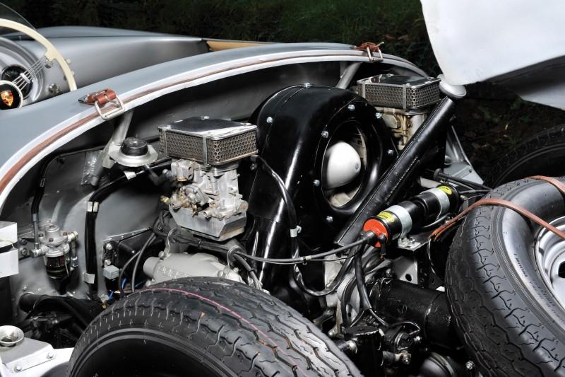
You're doing some pretty cool stuff. Adding those could make getting the engine in & out a greater challenge. Clearance is difficult as is the carbs, fan shroud and alternator have to come off and then you still only have a quarter inch or so of clearance if you're just pulling the engine. Just saying 😀
Pete
Thanks. The manual says to put the engine and transaxle in as a unit so that's probably what I'll do. Worst case scenario is I'll have to drill out 24 rivets.
I can't help you, my motor goes in from underneath, and I have no torsion tube.
Nice jobs on the pins/receivers!

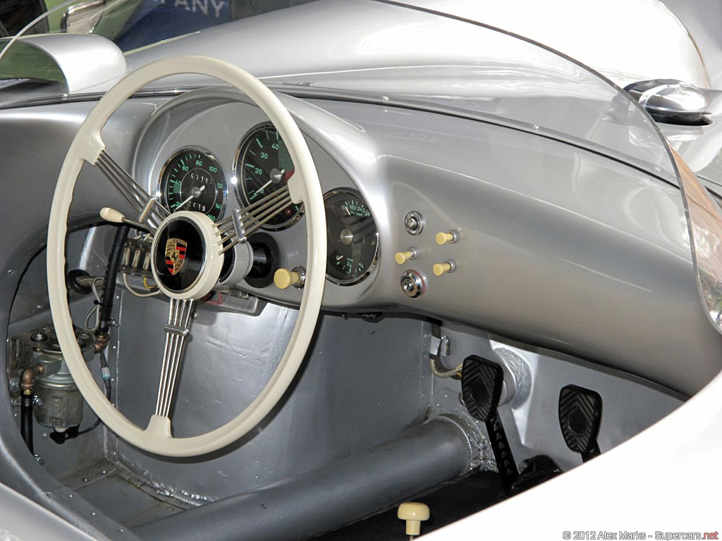
Tried to put the pedals in last night and it was not possible, so today I cut the floor section out of the footwell.
I can see now I'll be re-doing the MC holes so the pedals are even. You can see I cut out the "tunnel" plate to make room for the single gas pedal. What was there was perfect to just bolt in a Bug pedal set but why do anything simple when it's just a few 10s of hours to cut it all up and build it by hand from scratch?
Put the car on the lift and put the lift WAY up, and at the last notch I heard a "pop" and about a half pint of hydraulic fluid puked out of the cylinder. So that was cool.
I called Direct Lift thinking I'm needing a whole new cylinder and the dude there was like: How high was it?
All the way.
How often do you put it up there?
First time in many months. Maybe ever for that top notch.
Ah. So maybe some fluid got past the rear seal and has been in there a long time. Happens a lot. When the lift is up that high there's nowhere for it to go, so there's a bleed-off valve for this.
He tells me to get the car off it and cycle it up and down a few times all the way. Call him if significant fluid comes out after the second full lift. On the first one I got another half pint. After that, nothing much.
So I pushed the car back on the lift and continued hacking at it.
Such is today's shop drama.
Attachments
Images (1)
OK so the clutch and brake pedals are sort-of in now and sort-of level and that took all day.

Attachments
Images (1)

Nice to see you’re staying off the streets...... ![]()
I like that you incorporated a toenail emery stone for when your stuck at a light.
What are you going to do for a floor?
HAR.
I'll put the floor back in. I'll decide later whether to just do rivets or use threadcerts and buttonhead bolts.
Buttonheads would look wicked awesome... Jus' sayin.
Yes. The underside of the car will be unpainted aluminum and rivets. Probably allen screws in the driver's floor section, if only to facilitate my own sorting it out, since the dang pedals are all being cobbled together from detritus by yrs truly. I will post photos of it (the belly pan) when I'm done, because it's going to look like $4 million and, realistically, almost no one will ever see it again.
Pedals, today at 1 pm: 
That's how they gotta be for the brake pedal to have 8 inches of throw, which is what's needed for the dual circuit master cylinder to function in the event of a bad circuit.
Here's a shot of the situation at 4:30, as I was getting ready to knock off: 
Basically made the whole front unit of the accelerator pedal system today, though almost none of the welding's done yet. Since I'm working from (a very few) photos and no technical drawings, I spent much of the day setting or holding parts near each other and guestimating sizes and distances. I think this is gonna work and look about right. I'll bench test it tomorrow, tack it together and test it in the car.
Livin' the goddamn dream over here!
Attachments
Images (2)


edsnova posted:
...I spent much of the day setting or holding parts near each other and guestimating sizes and distances...
Geez, you're going to have the world's only 550 Spyder that's built like a Ferrari.
si fatto a la mano
You can call me Edsno.
edsnova posted:You can call me Edsno.
Bam.
Productive day in the shop, and inches from being done with the pedals.... Dang, ran out of wire.
Almost though. Just a few more tweaks to the actual gas pedal thing that your right foot goes on.

Moving the pivot point down. The hexbar only needs about an inch, inch-and-a-half of travel to get from idle to WOT. I was getting nearly 4 inches of pull with it like this.

Everything else is roughed-in: welded, ground smoove, holes drilled for mounting, etc. Now just needs a few nylocks and washers and maybe a cotter pin up top in place of the nut so it won't bind up or fall apart.
Oh, and of course a few more lightening holes.

Attachments
Images (5)


It's bloody amazing what you are doing, at least to my mind.
Here are a couple of shots of Henry's early-in-the-build-process pedal work in my car.
Notice the lack of a floor...as you found out, it's easier to do the pedals before the floor goes in.
Attachments
Images (3)


Thanks, and yup: It's quite a bit more involved than I had reckoned, but mostly because I've never really even looked at a pedal set before, let alone built one.
I have about 35 hours in pedal fabrication so far, with a few—five, let's say—more to go. With material expenses I'm way behind where I'd have been if I'd just sold off the stuff that came with my kit and bought the Fibersteel legit 550 pedal cluster for $900.
That said, if I ever have to make another set, it'll probably be a bit more than half the time. A third set would be quicker still and probably better.
It's therapy.
And...thanks to everyone on this board for all the encouragement. Hugely inspiring as we pass this milestone of finally finishing one of the first things I asked about when I got the kit.
Ed, do you attach a Morse cable to that accelerator contraption thingie? Or just a regular pull cable?
Very realistic approximation of an original on the pedals. You're gonna fool a lot of folks. I'm thinking realistically 2019 though. You've got a lot of work to do. I know you won't rush it.
Decided my accelerator pedal, using the Empi pedal base, wasn't good enough. So I dug through the scrap pile, got out the sledge hammer and the cutoff wheel and the grinder and the welder, and five hours later I had

I'll save the boring details for a blog post, but suffice it to say I'm pretty chuffed about the way this came out, and basically dumbfounded that Porsche made these this way in the first place.
Attachments
Images (1)

I really like your wood board "mock up" fixture ! I use wood mock ups nearly every time I'm making drastic changes. You would have laughed at the weird shapes of roll bars I made up and then used to roast chestnuts in my " Chiminea "on cool evenings.
You do VERY good work Ed...............Bruce
Ed, I've been following your build since day one.... It will truly be a hand built "Replica" Spyder.... Fantastic skills there man...
To Danny's question: the lever is drilled small for Z-bent Bug cable. Obs I could go with a ball fitting later. TBD.
Great to see that photo of the pedal base mockup.
I finally found my missing 1/2" stubby wrench.
Been at Frikkin Ed's all along!
When I lend something I put a reminder in my phone in two weeks if you can’t read a book in two weeks or use it in two weeks return It and borrow it later ![]()
wunderlist is a good tool too
So I modded that gas pedal one final time and here's the full saga.
belly pan.

Attachments
Images (1)


Attachments
Images (2)
Belly blog. "Keep the shiny side up" no longer has meaning for this car.

Attachments
Images (1)
Into punch-list for pre-paint prep: cut aluminum sheet for front bulkhead. Painted front bulkhead; smoothed fiberglass under dash, marked sides for torsion bar ports, smoothed horn pockets and rivet dits under front valance, retrieved gas tank; cut out scrutal intrusion, test-fit filler (hood hole needs embiggening).

Tomorrow: fiberglass. What I hope will be the last of it on this car.
After that: fit up the headlights, tail lights, license plate light and windshield.
This is happening, people.
Attachments
Images (1)
Fuel tank area filled. Light plinths marked. I have the "good" Fibersteel lights kit.
Cut the torsion bar ports. Got up under the front fenders to see about making the shapes right, and smooth.


Attachments
Images (4)
“cut out scrutal intrusion”
Ouch!
I don't even wanna look that one up....
Yeah, that sounds very... personal, Ed. ![]()
It's a scrotal intrusion you should be worried about, guys...![]()
Under the dash: nicely neutered.

Formerly:

Attachments
Images (1)
Yeah, but before the "scrutal intrusion" fix-up you probably wore "Top Siders"....
Attachments
Images (1)

It's a Spyder and big feet thing. I need to neuter mine.
Bought two hole saws today: 2.75 inches for the parking and tail lights, 4.5 inches for the tach. Hole saws cost!
Almost done with the glass/filler on and under the dash. Also got my torsion bar access holes done. 

Attachments
Images (2)
I just mark edge of hole I want and cut biggest hole with what I have then sand with a sanding drum on a drill.

edsnova posted:Hole saws cost!
Welcome to my world, buddy. Two guys in our little refrigeration boutique burn though a couple hundred bucks a month in tools. Anything with teeth or aggregate is especially prone to cost big money.
Hole saws are expensive for using it for a one time use. I pencil side the hole onto the fiberglass and rough cut it inside the line and use a drum sander on a drill to quickly finish it.
I respectfully disagree. First, you purchase the arbor(I bought Lenox), then individual saws as needed. In fiberglass work they LAST, maybe not so in Stan's line of work, but for the hobbyist they certainly do. I started out with the arbor and one saw to enlarge my turn and taillight holes for the original style lights. Now I have 5 or 6 different sizes. I do admit the larger ones are more expensive but I do like having the proper tools for the job.
I have used the saws many times since they were purchased for a single use.
... and that's how it is with tools. If you buy the right ones, you'll surprise yourself how often you'll end up using them (as long as they aren't super-specialized). Tools are just good to have, even if you don't use them for months (or years) at a time. That's why Dr. Clock's giant shop purge shocked me in the extreme.
My dad would spend an inordinate amount of time working around not having the tools or materials he would've liked for a particular project. My theory is that tools are very, very cheap (no matter what they cost)- it's labor that is horribly expensive, even if it's your own.
You only have one chance at this life. Spending time uselessly trying to make the wrong tool work is not how I want to spend mine.
fwiw, most of the hole saws I have are from "the Dr. Clock Collection."
I thought was for a one time usage , but totally agree with Danny and Stan too that I should have kept some of the Speedster shop inventory. Nothing more demoralizing than having to go buy jack stands from NAPA .........
I agree with Stan I find myself having more time these days and I have been accumulating some practical tools for my Harley’s woodworking and of course my car since I have more time I have my favourite stores that I go to these days you can receive their flyer in your inbox and if you find something that would be handy for a job that you’re doing or you foresee doing then you can buy that quite reasonably
A few years ago I got myself a really nice Dewalt tablesaw that can cut 24 inch i am having a little fun Building all my garage cupboards with it
Dr. Clock so wisely wrote: "Nothing more demoralizing than having to go buy jack stands from NAPA ........."
And so we all see another example of the "Circle of Life."
Build and have a nice home, have a few kids, a car or two, set up a nice shop to build things for the kids and then fix the stuff that the kids break. Then the kids get lives of their own and are gone so you"downsize" to a smaller home and, in the process, can't justify all that "stuff" that used to take up a lot of shop/garage space and was so important to you "back then" so you jettison it to save space. After moving in to the new place and spending days sitting around with nothing to do, you go nuts and break things, just so you can go out and get some tools to fix them. It's a primal urge that can not, nay, should not, be ignored.
I did that three times now, but the last move was way better because we sold one place and kept the other so everything got consolidated here. THAT's why I'm out of space for any new (read that "large space sucking") tools.
I'm just waiting for projects to show up needing my full set of 1" drive sockets (1-1/4" to 4"), or my set of four sizes of ball-joint pickle forks, or my 10" table saw, or my 200 lb. blacksmith anvil, or my hole saws from 1/2" - 6", or BOTH a MIG and TIG welder (and you know how well I can weld) or a large Oxy/Acetylene torch set-up or.....
You get the idea, but Heaven forbid, the day after I give away a tool, I'm sure I'll desperately need it.
I regret that I have but one "like" to give Gordon's comment. Tools should never, ever be "gotten rid of".
Ever.
They can tend to “walk”, though, so I now keep the shop locked. Used to let neighbors use what they wanted but found tools going out and not coming back (or coming back damaged). Now only my son and my “second-son-from-another-family” neighbor next door get in. Order has returned to my “Circle of Life”.
And whassup with Google? They’ve now made it far tougher to poach images!
No “Rafiki” for you guys!
Screen shots still work ![]()
Yeah, that's true, but that's so............ 1990's, don'cha think?
Stan Galat posted:... and that's how it is with tools. If you buy the right ones, you'll surprise yourself how often you'll end up using them (as long as they aren't super-specialized). Tools are just good to have, even if you don't use them for months (or years) at a time. That's why Dr. Clock's giant shop purge shocked me in the extreme.
My dad would spend an inordinate amount of time working around not having the tools or materials he would've liked for a particular project. My theory is that tools are very, very cheap (no matter what they cost)- it's labor that is horribly expensive, even if it's your own.
You only have one chance at this life. Spending time uselessly trying to make the wrong tool work is not how I want to spend mine.
Basis for the axiom "...you're more likely to injure yourself trying to cut with a dull knife than a proper sharp knife." ![]()
But it makes me wonder how many of us have had tools for years (decades, even) that we haven't touched and yet still refuse to pitch? I have a bunch of Flathead V8 specialty tools from my Hot Rod days; Valve spring tools to get the keepers on, corkscrew wires for replacing the mainseals, etc. I still have a Sears Dwell/Tach that only goes down to 6 cylinders ![]() and a bunch of tools for snowmobiles, but I still use the very same soldering gun I used to build my first Ham Radio transmitter back in 1960. It's got a lot of electrical tape holding it together, but it reliably works.
and a bunch of tools for snowmobiles, but I still use the very same soldering gun I used to build my first Ham Radio transmitter back in 1960. It's got a lot of electrical tape holding it together, but it reliably works.
I refuse to give up the 10" Skillsaw that I keep up on top of my shop cabinets, though. At about 15 pounds, it feels like you're hefting a small car but it built my Dad's house and still runs. I have, and use very often, his carpenter's hammer, too. That's not going anywhere, either.
FWIW, I have had a small soldering iron for, oh I dunno, 35 years. Just bought a new one, with a nice little stand, variable heat transformer, all of which the old one did not have, and so made using it a bit of a trick, sometimes. So I was like Stan's father, kinda -- work around, make do. I find the older I get, the more I don't like that approach. Need a tool? Go buy it. Nothing quite like having the right tool for the right job. Not saying there isn't a certain pleasure from jurry-rigging something up to do a certain thing out of stuff just hanging around. [This latter approach seems to suit Ed a lot. No offense Ed.] Like the 2x4 disk brake pads I saw a pic of recently.
Slowly building up the tool kit. Many, many years of McGyvering everything (mainly from lack of money) have left me with some bad habits. But I do OK, mostly.
Put a scratch coat of primer under the dash today. I hate working with filler and stuff under there; it's just a fiberglass blizzard. So I'm gonna leave it a little rough, probably.

While I was down there (and to get away from the fiberglass blizzard) I made this nifty bracket for the floor-mounted dipper switch. 

I don't know what the right tools would be to make this, but the vice, a couple clamps, and a channel lock did the trick.
Here's what the real deal looks like (well it's mostly behind the clutch pedal in this shot):
Gonna have to figure out how to run both the floor and the signal stalk switches, I think. Since the lights will be on relays, I'm hoping it won't be too hard to do.
Trying to get the binnacle sorted for the new gauges and it's fighting me. The hole saws wobble and bind. The overall shape of the gauge pod is asymmetrical. The pod is also smaller than an original Spyder's. It's just eating up hours right now. But it's the kind of thing you can't half-ass like the finish of the underside of the gas tank cradle that no one will ever see.


Attachments
Images (6)
Old tool story.
In 1968, I was very young.
I'd just gotten my first brand new car and I intended to lavish upon it the very best service that money could buy. Which meant taking it to the dealer, right?
OK, like I said, in 1968 I was very young.
The geniuses at the BMW dealer somehow managed to screw up my very first oil change. I didn't realize it at the time, but this may have had a lot to do with me eventually becoming a cynical, bitter old man.
The gasket on the oil filter somehow got folded back on itself and the filter screwed down tight. It must have leaked, so the geniuses would have cranked down on it even harder until it didn't leak. Imagine how hard that would have been. And what it must have done to the gasket.
Miraculously, it held for a few miles. But then it didn't. And it didn't in a rather catastrophic way one winter's evening in the middle of rush hour traffic, in a Philadelphia neighborhood where you didn't stop passers-by to ask for help.
I decided then and there, I could do at least as good a job at routine maintenance as the certified geniuses at the dealership and went off to get some tools, to the only place anyone went for tools in 1968 - Sears and Roebuck. It was 'and Roebuck' back then.
Along with the basic socket sets, screwdrivers, wrenches, feeler gauges, and sundry shiny gizmos, was a gen-u-whine Roger Penske timing light. I think I've since figured out that both Sears and Roger Penske were learning the art of making money through branding. It's unlikely that Roger Penske was personally involved in the design or manufacture of my timing light.
Did I mention, in 1968 I was very young?
As it turned out, I was unable to use my gen-u-whine Roger Penske timing light to set the timing on my BMW 1600. Unlike every other car in Christendom, there were no timing marks on the crank pulley. Instead, there was, allegedly, a small ball bearing pressed into the edge of the flywheel which one was supposed to be able to see by pointing a timing light through a small cutout slot in the bell housing. Honest, I'm not making this up.
In theory, you'd point the timing light down through the slot, slowly turn the distributor, and at the proper moment, the ball would magically appear and you'd be timed. Well, maybe you would be, but I never was. Through another 31 years and two other BMW's, I never was. I never ever saw that freakin' ball bearing. To this day, I think there is a room full of technical writers in Munich laughing their asses off about the ball bearing on the flywheel timing joke.
So what about my gen-u-whine Roger Penske timing light?
Well, since everyone but Dr. Clock holds onto all their tools forever, it languished unused in a series of garages, basements, and attics over the years, in its original box. With cars being what they are today, I figured I'd never use it and someday maybe pass it on to the Smithsonian or maybe Madame Tussaud's wax museum.
And then, believe it or don't, one day about four years ago, I suddenly found this ridiculous new car in my garage with a brand new motor that had been designed in the 1930s. And it had a crank pulley that wasn't hidden behind some dumb plastic shroud. And a distributor I could adjust. And on the crank pulley were - timing marks! That I could actually see!
So, I finally discovered, after 46 years, that Roger Penske allowed his name to be stuck on a halfway decent little timing light.
Never throw away good tools.

Attachments
Images (1)
Oh, dem fu#!ing hole saws. Ask Drake about those . . .
There has to be a better way.
Sacto: excellent story, well said. My timing light was a 6 v flashlight bulb and bare socket I connected to two aligator clips and would clip across the points and slowly rotate the engine until the light went out and check to see if the pulley was at the right position. Adjust dizzy as needed. Talking about a '56 A Coupe here, and conducted precisely as my Owners Manual advised. Called static timing, and was goodnuff. Going to a dealer, or even a decent P-car garage was out of the question. While you were merely young, I was both young and poor.
El Frazoo posted:Oh, dem fu#!ing hole saws....There has to be a better way.
Yes, there is...

Attachments
Images (1)
PS: I upgraded my timing light tool kit along the way with a neon bulb sort of thing that you hooked in line with the #1 high tension lead from dizzy to spark plug. Allowed dynamic timing setting. The flashing light was rather dim, actually, and so the operation was best done in a dark garage. Did I mention I was poor?? Ergo, no garage, so this tool was best used at night. I actually bought a timing light much like the one you show here a couple of years ago and really upped my game. Came at a time when I was/am not so poor, so could spring for this high-tech version with very bright light. Also I now can afford the garage. And can do the deed whenever I want.
As to the milling machine, a half decent drill press and properly applied C-clamp might also work. There are many things I could accomplish with unlimited money and space.
Thanks, Kelly.
The timing light procedure was described in the car's owner's manual (not the shop manual).
There were detailed, illustrated procedures for doing everything - carb adjustment, valve clearance, plug and point gaps, - even brakes! I guess they figured most owners in Germany then would have a timing light handy.
I think Porsche had a similarly detailed owner's manual for the 356.
Different times those were.
Reading everyone's story of stocking piling tools made me smile as my dad did the same. He believed in having the right tools and made every excuse to buy more. He passed a few years back now but it made me think of all the tools I am still trying to figure out what they were used for as I inherited most... as my siblings had no interest. I have a valve spring compressor that I have no idea what it works on... Maybe it's for that flathead someone mentioned...then lo and behold Sacto pulls out the gen-u-whine Penske special timing light. The same one dad and I used on every car we worked on together and now resides in the "Sears Craftsman" rolling tool box in my garage. Great story Sacto!
Attachments
Images (1)

Blog update on my Spyder build.
Fuel tank, fuel cap (properly located), is coming together finally after 10 months.

Anyone catch the Spyder's oil filled heating system Ed installed ?
El Frazoo posted:As to the milling machine, a half decent drill press and properly applied C-clamp might also work. There are many things I could accomplish with unlimited money and space.
It would work in a pinch but say good bye to the arbor -shaft bearings as they weren't designed to take a lateral load .
Regarding holsesaw wobble:
If you're having trouble, drill the pilot hole first (without the holsesaw on the arbor). Put the holesaw on the arbor, and spin the drill backwards. Once you've made it through the gelcoat and into the glass about 1/8" or so, reverse the drill to run forward. DON'T PUSH ON THE DRILL very much at all-- let the bit do the work. you'll get a little breakout on the back, but you won't chew up the front surface, and the saw won't "walk".
El Frazoo posted:Oh, dem fu#!ing hole saws. Ask Drake about those . . .
There has to be a better way.
There is. Regarding my good friend Cory's toy holesaw-- the holes he drilled look like a beaver chewed them because he bought the world's cheapest holesaw with a single knife orbiting the pilot like a sputnik satellite. The ones on Ed's bench are Lennox, which are pretty close to the best in the business. Morse is OK, and I've used some diamond-impregnated bits for drilling ceramic/porcelain tile, but that's not the appropriate tool for the job. Getting the right tool for the job is the key to doing a good job.
I still have a set of babbit bearing scrapers and some shim packs. I use one of them as a de-burring tool....Repurposing ?.............Bruce
Stan, we tried to tell him, but he doesn't listen with those ears on his head....
When I was down there, he tried to get me to drill a hole in his diamond plate floor with a cheasy harbor-freight-looking corded drill and some cheap hole saws that might work once, in thin wood. I declined.
fwiw, @Stan Galat, the 4-inch saw seems to be ovaled slightly. It's not "walking." And my issue so far is getting clean and accurate holes in this 24(ish) gauge aluminum sheet, not the 'glass. Still, good tips. Hole saws require more finesse than I at first realized.
The way forward, I think, is for me abandon the scrap pile and crack the wallet for some thin aluminum plate, as the job requires.
Sounds good, Ed. The gauge panel I have is a little thicker than what you are trying to use in your pics. I believe it's also laser cut. I know Greg has them(and they really aren't that expensive: $75?), but the holes may need to be enlarged if you're using original diameter gauges.
Ed, that fuel filler is one of the few things on my new car that I wish were different. Looks great!
I hear you on the "ovaled" holesaw. It's likely round, but with the arbor hole slightly off-center. If that's the case, take it back to where you bought it, and get an exchange. As you said, they aren't cheap tools.
BTW: I'm loving the progress reports. Good job, sir.
I had one that wobbled, turned out to be an undersized bit and when the Allen screw was tightened against it , the bit would be slightly off center.
Paging Dr. Clock!
Oh, that's funny.
Alan. We were posting at the same time. I actually found the undersized bit one earlier. This one I'm using the same arbor for all three holes. The best-looking 4-inch saw wobbles just a bit. Fortunately there's another 4-incher in the box that spins truer.
Yeah, I thought that was pretty neat - equal heat for both pilot and co-pilot and adjustable, too! I suppose you could use it as a resin speeder-upper, too....Jus' sayin'.
Very thoughtful, Ed!
Ed: I had a set of hole saws from Lowe's/Kobalt that had that off-center arbor, too. took them back and complained mightily to the store manager of the day about how much time they wasted me and he gave me an equivalent exchange set of Rigid saws (which go for more $$$). Those are great. Usually I'm cheap-ish on tools, but all of those I paid dearly for are still with me.
I have found that hole saw wobble can be significantly reduced by drilling the pilot hole first and separately. Then installing a piece of 1/4 inch drill rod (or almost any plain steel 1/4" steel rod) in the hole saw. There are chip removal flutes that are on a regular hole saw pilot bit. Those chip removal flutes are what cuts the pilot hole larger as you are drilling due to side thrust. There's a lot of that on a large hole saw ! Even then, I think you still get a crude, rough hole, so I always go one size smaller and finish with a half round fine file or a cylindrical drum sander. Especially when the finished product is a show piece. I have pretty much found that hole saws always give you a larger hole that what the size is that's stamped on it ..............Bruce
Thanks, Bruce, and Gordon. I do pre-drill the pilot holes. But the idea of using a piece of smooth rod in the saw hadn't occurred. Good thinking.
As for taking it back.... well, it was one of Alan's, part of a box of used tools and stuff I paid not so much money for. So I don't think I'll be hollering at him too loud.
Bruce: Exactly!
A few years ago, I made a pinion nut wrench for rebuilding my transmission. It is like a sprocket, it has 16 teeth and 16 low spots the same width as the teeth. Inside diameter was metric, but close to 1 7/8". I cut the tool by drilling 16 holes in a circle(homemade circle jig), then cutting out the center with a 1 3/4" bit, as the wobble makes a bigger hole. Ended up hand filing the teeth to get it to fit, after lathing the inside diameter to the correct size.


Attachments
Images (3)

whelp,

Definitely a little tighter fit than the original, but the very best I can do with the materials and tools at hand. I don't think too many passers-by will point and laugh.
Also, 
Attachments
Images (2)
Ed, if you had not told me, how would I know? A millimeter here, a millimeter there, who's going to get all over that?? Looks like a good job to me. As to hole saws, there are hole saws and then there are bi-metal hole saws, so I learned just the other day. Bi-metal teeth seem to work much better. Also, using a new one is the ticket too. Had to drill a 4-1/8 in. hole through a double 2x10 band plate to vent a dryer. Use new saw, drill pilot first, go slow. Let the tool do the work. All will be good.
"Oil filled heating system"?? AKA "an engine"? There is so much gee-whiz stuff going into this build, its hard to keep track.
@El Frazoo scroll back and check out the free standing radiator ( under dash) Ed stole from his Grandmother's house.
More rivets. The interior aluminum is now done. Also dry-fit the pedals one last time to make sure it all fits. Propped up the Empi gas pedal as a possible dead pedal but I don't think so. The dipper switch works good.

All the bulkhead-to-frame tube plates are done now, including those in the footwells. Rivets on rivets, but they look cool. Unlike that Empi gas pedal/footrest.

Yesterday I spent time fiddling with the fuel filler.

Sits a little low so I shimmed up the whole tank. But I didn't like that so I made a 3/16th steel flange for my buddy to weld to the top of the tank over the sheet metal he spent a lot of time welding earlier.

Also test fit the headlight buckets. I'll be damned! They fit nice. 
Ordered some H4 halogens to fit in them.
Also today I got my rear latch cover plates:
One I locate those I'll be all-but-done with the drilling of the holes on this car. After these it's down to the license light, switches and emblems.
Speaking of switches...

This is next. The car's pre-wired but two of those already-wired switches are marked "lights." An adventure, this is.
Attachments
Images (7)
Please..... No EMPI dead pedal. ![]()
Empi dead pedals

Attachments
Images (1)

Why don't you try one of my folding foot pegs ? It's out of the way when not needed.
Attachments
Images (2)


I'll sort out the dead pedal later, guys. Thanks.
A dead pedal that is fabbed up by you to match what you already have is the only way to fly.
Car is looking good. Coming together nicely.
I totally agree with Gandalf. Home Brew something cool.
Bruce, that's a very clever design. Simple and totally does the job.
I see Ed doing something more in the "Steam Punk" vein - Something that will take, surprisingly, HOURS to complete. Kind of like my hand-tooled, polished Stainless Steel, driving light brackets that took about a day each:

Attachments
Images (1)

Didn't work on her the last couple days. Power outage Friday afternoon lasted until noon today, and had to do some maintenance on the wife's DD.
Did get the fuel tank back to the welder with instructions on how to get the flange on it. Also roughed-in those rear latch covers.
Guys, I'm looking for the door striker bolts now. I don't seem to have any in my boxes of parts & still not exactly sure where the correct part is from. Seems to be a single bolt, about 1/2-inch thick, with washer. Any help appreciated.
Trying to make proper clam stay now.


Gonna do it again tomorrow out of pressboard and make the frame side mount for it too, then adjust before doing it in aluminum. If there's any interest, I may produce a scale drawing of these parts as well when I'm done.
I also knocked-out the brake cooling ducts today because, well, why not?


Attachments
Images (6)
Somebody asked me a while back what-all my spare-tire carrier frame weighs. The answer is 8 pounds, three ounces. With fasteners we'll call it eight-and-a-half.
And that includes the bracket for the clam stand-off.


Attachments
Images (7)
@edsnova Very cool! Thanks for sharing all these progress pics, Ed! Very informative. ![]()
edsnova....Very good pattern and prototyping ! I appreciate the time you are taking to photo your projects and progress. Makes for interesting reading and looking at the details.....Bruce
I'll be filing today in the hope that this first try will actually work. So far it looks good.
If it does work I'll trace everything onto paper and include measurements so future builders can just cut them out or, better yet, have someone do it for them on a waterjet.

Wow! That is amazing craftsmanship!!

Drawing's available to SOC members.
Attachments
Images (1)
Drawing's what? ![]()
![]()
Drawings of the rear clamshell holder-opener-thingy. Not applicable to you Speedster peeps.
I definitely need to make one of those. Drawings would be awesome.
PM'd.
The speedster ones are still available commercially.
Carey makes these now as well.
I've always thought those latching hinges were pretty slick.
It's amazing, Ed, that you were able to cut out some simple shapes, put them together, and actually make them work as intended.
The thought that went into the original design is impressive. How did they come up with something like that out of thin air? How many other builders would have bothered? I guess the hinges are a tiny example of the design principles at work throughout the whole car - how to do more with less.
Keep up the good work. Your detailed progress reports are revealing parts of that design that many of us would otherwise never get to see.
Thanks, Mitch.
Here's the Beck part, which (last I checked) was a $350 option on your build, $250 out the door. It's a beefier part and a stronger design than mine (albeit not-quite-period-correct), with a couple pounds weight penalty. If I had a job I'd probably have bought it rather than spending the 13 or so hours copying the original part, enjoyable though they were. It helped too that I already had the perfect piece of 1/4-inch thick aluminum plate and a big sheet of 1/16 stainless just loitering around the scrap pile, so my material cost is only about $4 in fasteners. Your mileage may vary.


Attachments
Images (2)


Yeah, that's the one I have on the new car. It really looks the part, and yes, it's steel. It isn't that heavy, though. It is VERY cool you made yours from aluminum. And by hand no less!
I painted mine with hammered silver, to look more vintage. I really like the way all the parts look with that finish on them.
I drilled an extra hole in mine for a lock pin I keep in the driver's door. I worry that one day at a car show the wind will hit it just right and lift it up enough then SLAM down it goes. Or somebody will lean on the clam and mistakenly push it up, then SLAM! So now I don't worry at all, just slip the hitch pin in and lock the bail.
Interesting, given the pic shows a bolt through it. He must've added that after you got yours.
I had the same concern; added the lock pin to mine the other day. Re-used the chains that came on the door handles Carey sent me. I'll probably rivet the chain end in next to the clam stay, and drop the pin in one of the spare tire mount lightening holes for storage. Then it's right there when I pop the clam open.
BTW, here's what's next:

Attachments
Images (1)
Nice, I have some of that too but never installed it. I think I have 6 feet or so, but it's used so not all pretty like yours. I was going to attach it to my trailer hitch for when I flat tow the Spyder, but never did.
Good luck installing that around the suspension, it looked like too much of a PIA to me. Are you doing the full engine undertray as well????
I plan to make an undertray but that job really is for after the wiring and plumbing and painting is done. Brush guards are installed. Clam latches and cable remote too, but the passenger side is sticking open. Could you (Danny) send me that pic of your double-spring rig again?

Attachments
Images (1)
Clam lid now latches tight and unlatches with the flip of a lever. We're getting down to brass tacks.

Attachments
Images (1)
Looking good Ed.
Been away from the project for a few days. Itching to get back into it. Updates soon...
Back at it today. I made the throttle linkage that goes on the firewall (changes direction of the cable-pull and makes it a "push," per the original). Also put a throttle stop in my gas pedal rig. And I cut out a set of seatbelt mounting tabs to weld in to the chassis.


Attachments
Images (4)
Got my seat belt anchors welded in today.

Also roughed-in the two main hard fuel lines, including (of course!) the period-correct Italian-made glass bowl fuel filter/pressure regulator (apologies to Stan).


Attachments
Images (4)
Wow Ed, "U Da Man" some awesome work you've been doing.
Pete
Thanks, Pete.
Oh yeah, we're into the fun stuff now.


...apparently the above is wrong because there is no "bubble adaptor" on the clutch mater cylinder. Two such adaptors were supposed to be supplied "with the kit," according to the build manual, but none were.
Anyway, I am enjoying learning the finer points of SAE/NPT vs Metric flare standards...Anyone wanting to accelerate my learning curve, I'm all ears.
Attachments
Images (2)
No matter what you have , how much you have .....you never ever have the right fitting...It's called Ed's Law :~)
Wilwood uses 1/8" -27 for all their stuff. So you need a metric female(10mm x 1.0 I think) to male 1/8 pipe thread adapter.
If you do the AN flex hoses, they are AN-3 usually and they have adapters on the ends. Some guys will tell you that they must be done with no adapters but they work fine. You can get hoses in any length you need, I used Pegasus Racing. They also have any adapter you could possibly want. Pipe thread, male/female, bubble, 45s, 90s, banjo ends, all of it.
I cheated. I used a guy in town that had all of the stuff needed to make any connection you had and he did it for a living. Same guy that did "Tubes and Hoses". Ask the NAPA guys - they'll probably know of a shop near you.
Thanks, all. I flared a bunch myself today and roughed-in all the hydraulics. 
I found one adaptor in the coffee can fulla brass junk I bought from Merklin last year, and maybe that was all I needed.
Then again...we'll see when I fill the clutch reservoir and try to bleed it, I guess.
Attachments
Images (1)
Just make sure your brake pressure switch for the brake lights is screwed into the proper port, and that one of the front wheel lines ISN'T in the switch port!
Oh yeah, and install two switches(and make the wires long enough to reach either), because it isn't a matter of if it will fail, it's when.
Ah... Good point. TR Manuel says block the front top port but of course that's the second front brake line port, isn't it? And the two midline ones are for two brake light senders.
Keep those advisories coming, gentlemen.
The brake line ports are larger, the pressure switch ones are tiny. Look at it, you'll see what I mean. Been there, done it wrong, went back and fixed it!
As a man, I seldom consult the instruction manual, and here's Exhibit A as to why!
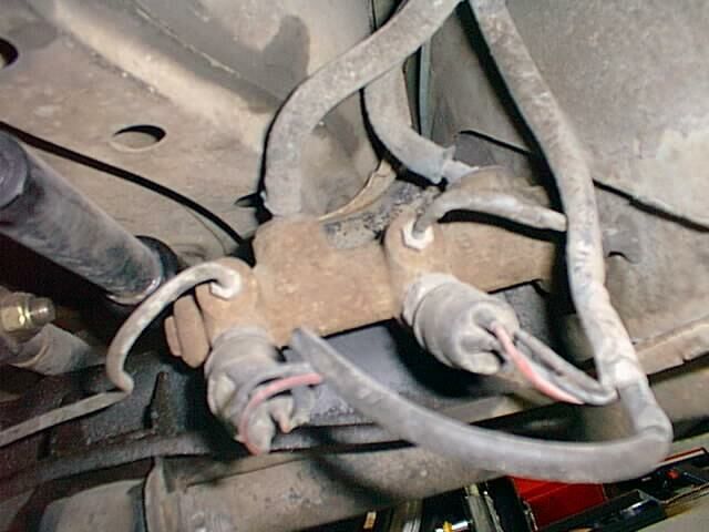
Whelp, the ports in this MC all appear identical. Mine has the number 113611015BD cast into it and the words "USE THIS" sharpied on the other side. Looks like this one, which is a 20.6mm 4-wheel disc conversion MC.
Think I'll move that left front wheel line to the top port, screw signal switches in the middle ports and call it good for testing.
UPDATE: on closer inspection, three of the five ports appear to be restricted: down inside the small hole you can see there's a smaller hole.
So the bottom ports, front and back, are "large" (unrestricted) while both middle ports and the front top port have the smaller holes.
I have seen photos of VW MCs rigged up all over the internet and I don't think I've ever seen a T fitting on front brakes. Always two ports. But if my MC is typical, always one of those ports would be flowing about 1/3 what the other flows.
UNLESS the large ports on the bottom are exclusively for the switch?

Man, I'm dumb.
Here are some crappy shots of my MC.


Attachments
Images (3)


you mounted it sideways! I didn't even know you could do that.
Thanks.
Next order of business: Those with the Fibersteel (or similar) original 550-style E-brake: how do you route your cables and/or through what and/or what is the cable pn?
Just got out the cables from the kit and I believe they are standard swing axle bug cables. They fit the brakes neatly but appear on the short side. Do you-all have extenders? What's the end hardware that interfaces with the stick?
More significant: most of the cable is unsheathed. There's no way to get from the brakes to the firewall with the sheathed part, so the cables would tend to saw through whatever you routed them through.
Looks like the way forward is to get a 1/2-inch steel pipe or tube (conduit, maybe?), Y it into the firewall and extend it to the flexible sheath in such a way that it won't interfere with the engine/exhaust, etc.
But before I start, I'd love to see how some of you have yours routed. This is particularly true if I'm thinking wrong.
I didn't mount anything, it came like that. But, it does make it easier to replace the brake light switch when it does fail. I didn't have to rebleed the system when I replaced mine. I did add a few drops of fluid to the hole and I prewet the business end of the switch before I installed it though.
My E-brake cables run through two steel tubes from the cockpit, through the firewall then left and right along the firewall, then they turn down the frame towards the brakes. I can send pictures, but If your trying to duplicate what they did back in the day, it might be better to find some vintage shots.
"Looks like the way forward is to get a 1/2-inch steel pipe or tube"
Maybe 3/8" steel brake line from NAPA? Easy to bend and easy to weld.
Thanks Carlos and Gordon. Def would like to see pics.
So I found the threaded rod that came with the e-brake handle; shortness of cables is not longer an issue.
In the box was also a piece of steel pipe that just fits over the flange ends of the cable sheathes. I already cut a little off to make something or other, but it looks like easy to find stuff. Harder to bend than 3/8 brake line though; hoping I won't have to bend much.
I've used 3/8" steel tube from Lowe's etc. when I needed to replace cable tubes
You know........Every day is like Christmas at Ed's shop with all of the stuff he keeps finding.
This is what my car looks like. It's a coil spring instead of a torsion spring like yours, so I have a little more room in that area. You also have more of a fiberglass shelf than I do. My rear hydro brake lines also "T" at the firewall, which I think is typical.

I would like to redo my fuel line situation in the near future. Lessen some of the rubber hose. I also prefer the spring clamp versus the worm drive clamps. I also need to shield my clutch hydro line in a spot where it gets pretty close to the exhaust.

Where the two tubes come through the firewall, I would've liked them to have been stacked vertically instead of side by side, and a little closer to the center of the car. This would make for a little more clearance with my passenger seat.
When I bolted the rear of my seats to the floor, and tilted them back, I had to make a metal shield so the turnbuckle on the cable adjusters wouldn't tear up the leather on the seat. This might be a point of interest for you since you have the opportunity to correct this, if it applies to your seating situation.
I think your seats will be farther off of the floor than mine are, so you might not even have an issue.
Attachments
Images (2)


HUGELY HELPFUL! Thanks. This is just about what I was thinking, but getting confirmation makes it a lot easier to proceed.
Ed, I believe the ports you want to use are lined up with the fluid input ports and 90 degrees to them. The ones at a 45 degree angle are for the brake switch or switches. I think one of mine is plugged and I only have one switch.
With respect to the rear e brake tubes, mild steel is fine. You can bend it quite easily if you heat it to a warm red with a MAPP torch and bend very slowly along as you move the heat. Heat the inside of the curve more than the out. MAPP gets hotter than straight propane. I hope these pics help, I don't have a good one of my MC.
Fuel lines are on the bottom, then the clutch line, the ebrake tubes, then the brake T on top above the shifter cables. You can see the metal fuel lines going up the firewall with my backwards Ford filters(with nitrile condoms!). Like Carlos, I prefer minimal hose(German woven cloth) and I used the spring clamps. Not a single worm clamp in the fuel system.
I made a T from aluminum for the Ebrake and welded some 1/4-20 nuts to the tube on both ends. It works well, keeps it low and away from the seat.


Attachments
Images (2)
In the last picture you can see the aluminum angle I used to lift the front of the seats up.
Also very helpful, thanks. I can see your seat belt anchors are about like what I made too.
Again, I say: seeing these details on other cars—cars I know are done well and that work—means the world to me.
E-brake tubes are bent and welded in with brackets. Wrecked my new clutch line with the big drill whilst doing this but I have another long line to pop in there.

Attachments
Images (1)
Are you getting better than me at welding yet?
Of course, Marty Feldman in "Young Frankenstein" was a better welder than me, too.
I'm just giving you encouragement, here.........
I don't know if I'm better than you, Gordon, but I'm def. better than me a year ago.
My buddy-who-welds-all-day-for-a-living's due in the shop in the next few weeks to use the lift and I'm going to show him my seat belt anchors first. I'll let you all know if he laughs and redoes them. 
Attachments
Images (1)
Looks good Ed, but your tube bends would look nice and smooth with some heat....
edsnova posted:I don't know if I'm better than you, Gordon, but I'm def. better than me a year ago.
My buddy-who-welds-all-day-for-a-living's due in the shop in the next few weeks to use the lift and I'm going to show him my seat belt anchors first. I'll let you all know if he laughs and redoes them.
That's why the "grinder" was invented!

Attachments
Images (1)

Even better than the grinder is to massage MIG welds afterwards with an Oxy-Acetylene torch to smooth the welds out. You can tell the difference between smoothed and well-done welds in the first place, but they definitely look nicer!
Truth be told, I'm not really as bad a welder as I make myself out to be.
I'M WORSE! ![]()
E-brake is in with cables and tested. It pulls 'em. Will need a little fettling still but it's basically ready for grease and final install.
Throttle cable comes in a few days. Also battery cable. I'm going to try and tighten up all my fluid lines and test my flares and stuff ahead of that.
From there we're into wiring and final body prep and paint.
Still awaiting delivery of the upholstery material, however.
Attachments
Images (1)
DannyP posted:Looks good Ed, but your tube bends would look nice and smooth with some heat....
Agreed. I'm hoping those dented tubes aren't a deal breaker when the for-sale sign goes up.
"Agreed. I'm hoping those dented tubes aren't a deal breaker when the for-sale sign goes up. "
WHAT?!
Top of page 10 Lane....
edsnova posted:DannyP posted:Looks good Ed, but your tube bends would look nice and smooth with some heat....
Agreed. I'm hoping those dented tubes aren't a deal breaker when the for-sale sign goes up.
Taking a lesson from Dr Clock et al...
DannyP posted:Top of page 10 Lane....
Danny: I don't Lane was referring to the bent tubes, rather the 'for sale' comment.
Ed's reason for building this has been to sell it. That and gain some knowledge along the way about building Spyders.
Aw hell. 😡
i figured this work of art was going to be a permanent fixture.
As much as I would love to own a Spyder AND Bridget, this car was bought to build and sell. It's a beta test for a Merklin-like side business I conceived when I still had a regular job (and when Alan was about to be "retired" and we know how that turned out).
It's also a beta test for a lot of my own personal theories about how true-to-Wendler a Beck-design Spyder replica can be made to look and feel (by a guy who doesn't actually know what he's doing).
Turns out, these two beta tests are in conflict, as Alan warned me they'd be.
If I were smart, and had followed Alan's advice, I'd have done a simple, clean build, finished by mid November or early December, titled, registered and sorted it, and have it listed already at a decent price that would net me a decent profit for my hours. But no.
I wanted to make a special car.
And so here we are. You can call me "Special Ed."
At this point I think (pending upholstery) it will be done in late spring and listed after that, after peak season, at a somewhat-higher price than would have been possible without all the detail work and rivets. And at that point we'll probably see how right Alan was.
Meantime, though, I'm enjoying myself quite well.
Today I finished off the E-brakes, then took them apart. Then I finished (again) the clutch line, tightened-up the fittings, filled the MC, bled and tested. And it works.
Which means my flaring skills might just be OK after all. (Just like my flux-core welding skills).
Checked the shifter and managed to get all 4 gears and reverse, so after I drill just a couple more mounting holes to keep it all solid (and fiddle a bit with the reverse lock-out), that's coming out as well for prep and paint.
In non-Spyder news, I also arranged today an editing gig for Friday—$250 for six hours—and applied for (yet another) tech writing job.
Rest of today will be on little stuff. Like, the front brake hoses need a wider groove at the inside fitting in order to work with the stock retaining clips. It's either that or grind off the powder coat off the frame under there, and I ain't doing that anywhere I don't need to.
Little stuff like that eats up a lot of hours. I mean, I could skip it, probably, and get away with that. But nah.
And that's why I'm serious when I say "dented tubes...hopefully not a deal breaker." I've made a lot of little mistakes on this car. Just like any builder on any car. And after a while on a build you can lose sight of whether a given glitch is a super important, glaring blunder that will make people point and laugh,* or is something that literally no one will ever notice.
My usual motto, "good enough for who it's for," is not applicable. Which is why I want everyone here to mix in a little vicious honesty with your applause.
Thank you.
*Some may recall a surly dude who bragged all over the site about his Speedster build and engine building prowess, who shimmed his windshield in with I-can't-even-remember-what, and then showed-off his handiwork to all of us.
Update:


Attachments
Images (2)
Ed, I’ve heard Carey complain about how hard it is to find skilled folks with a good work ethic. Ever thought about moving to northern Indiana? 😬
I consider that a mighty nice compliment, Lane, but no. My wife and I already live a bit too far from her job, and Indiana is way the wrong way for her commute to work.
Special Ed wrote " And after a while on a build you can lose sight of whether a given glitch is a super important, glaring blunder that will make people point and laugh,* or is something that literally no one will ever notice."
That must have been the philosophy of "Horst" and "Gunter" at the Porsche factory when building the Pre-A 356s. Especially how the front fenders aren't exactly mirror images (neither are the doors) and how the hood handle is 1/4" off-center on a large percentage of the cars. Maybe Horst and Gunter had eyes like Marty Feldman...

* You're 'special', Ed, because when you do something you do it as if someone cared. "Texas George"? He didn't have a clue about anything like that.
Attachments
Images (1)

"Horst and Gunter" had liberal access to beer during breaks and lunch..... Some of those breaks went 30 min. , and lunch often went 2 hrs. German National Standard.??
Little stuff today: Tapped another hole in the floor to make the e-brake handle stay put, re-routed the shifter cables a bit to make room for the engine, dry-fit the accelerator cable, made brackets and stuff for the brake and clutch lines and mounted the Accusump. I also made a plate to mount the seat heater switches behind the shifter.
It's all starting to look pretty tidy and reasonable on the firewall and on the floor of the tub. I still have to make a few tabs for the wiring harness and the fuel line, plus some reservoir mounts in the frunk, but this is all fun stuff.

The bad news: The lift is leaking at the main seal. Dang.
Attachments
Images (1)
"Seat Heater Switches"?!?!?!?!?
Somehow, I don't think James Dean would approve......
But then again, he just might!
Great stuff again Ed. It could be a challenge to get your motor in/out with the clamshell seats you made. I have taken mine out twice now and there’s really only about a 1/4” clearance from the top of the fire wall if like me you take it out separate from the trans.
Pete
Gordon Nichols posted:"Seat Heater Switches"?!?!?!?!?
Somehow, I don't think James Dean would approve......
But then again, he just might!
He would be 87 years old and whole heartedly agree that seat heaters make the back feel a little better at that age.
-=theron
Speaking of wind breakers. Who has one attached to their roll bar in a Speedster ? I'm working on a roll bar now and am thinking about welding on tabs for one before I get it powder coated. Photo's would be nice..............Bruce
I have one. I'll try to find photos. Mine is a CMC rollbar that was already painted and installed so and I used the window channel used in a car door to let the glass ride in it going up and down. It is notched and flexible enough to bend around the top corners of the roll bar/glass and gives it a finished look. Used the same stuff on the bottom and simply drilled and tapped the rollbar for screws to hold everything together. Got it at a glass place that does auto glass. Works great.
calmotion posted:@Theron I had them installed and love it. Nice addition. Next would be the wind breaker behind the seats 👍. I think James Dean won’t like that either not a good match with the hair style 😎
I have them too. I don't give a whit what Dean would have thought. Unlike some Spyder guys, I dislike the association.
Ed, keep on trucking.
I hear you on the engine-in/out, Pete. Plan to do initial install with the transaxle attached, but I may swing the lump over the back of the car first just to see if it's possible to put it in alone with those clam pin receivers there.
Well here's another pointless thing I'm making which is ruining expensive tools.
Anyone recognize this part?

Attachments
Images (1)
Ed:
Winston Churchill once visited a manufacturing plant entrusted with producing war goods during the start of WWII, and seeing the ability of the workers, wryly commented, (in opposition to the normal phrase):
'Give us the job, and we will finish the tools'. ![]()
If I'm not mistaken, Ed, that's the drilled aluminum bracket that was used on the 550 to support the 'For Sale' sign.
Hood hinge?
Bruce! I sent you a PM with DIY instructions for fitting a rear windblocker in a rollbar.


Attachments
Images (2)

Oh.....It's the Great Big "V" thingie!
I shoulda reconized it right off..... ![]()
I know, right? Who on Planet Earth is unfamiliar with this iconic component?