
Speedster jobs list
Ok, first off, forgive the long post! There’s a lot to discuss, and the more info I give out, the more help and experience I get back, so I welcome all comments (useful, sarcastic or otherwise!)

So, having checked most of the car over since I got it home the other week (and had a major oil leak to deal with), here is a start of a long list of jobs for the winter, in order of priority to:
1. make it safe
2. make it reliable
3. make it desirable

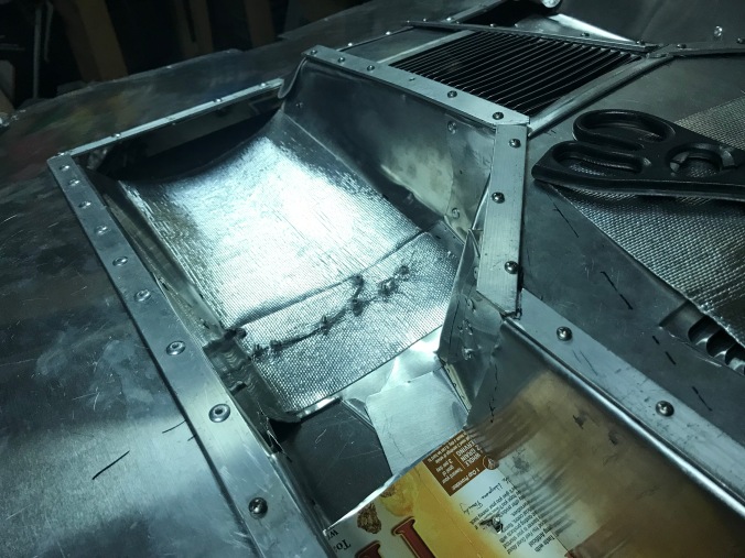
First off, the leaking oil cooler hose was fixed on Friday after picking up new hoses (thanks to Hyphose in Portsmouth for copying the old hoses). I’ve added more P-clips to better route the pipes more securely to avoid hitting the exhaust. I’ve also re-used some heat shield wrap as well for key areas.

Before I discuss other tasks, it’s funny how you often find one problem leads to another, because one shortcut for an old fix created a knock-on effect by fixing one problem only to create another.. I must admit I’ve been guilty of that in the past, either through lack of money, or time or just laziness! I’ve learnt the hard way that, at least for classic cars, do it once and do it right - its so much easier and cheaper in the long run.

Second main task is steering/suspension. Currently it’s far too stiff AND vague, so it’s a bit like a novice steering a barge down a canal, or ten pin bowling with the bumpers up.. Steering is nothing, nothing, over-correct left, nothing, nothing, over-correct right!

The steering box is covered in oil/grease, so whilst it’ll be ok for the very short term, I would like to fix this with new seals if possible, before filling with fresh grease. Is this possible? Is the steering box OEM? It looks like it to me.

tigermoth66_steering_box1

Even a quick adjustment over the weekend has made for a vast improvement in reducing play. I took the steering damper off whilst checking this so that didn’t affect the tests.

Another problem is the steering column - the shaft itself is slightly bent so rubs on the column/tube once every rotation. So I need to straighten the steering shaft. I may also have to widen the hole in the bulkhead because I think it was cut slightly askew.

I’ve now relearnt a lesson I’d forgotten from my early Beetle ownership 30 years ago - removing the fuel tank makes life a LOT easier for any front end work! Last night I managed to straighten the steering shaft by literally putting the boot in - climbing inside and putting some weight on the high part of the shaft (I call it the shaft because it’s the inside part of the steering ‘column’, which I think of as the outside tube the shaft resides in). I then replaced the old urethane rag joint/ steering coupler with a rubber OEM version - much better!

tigermoth66_urethane_couplertigermoth66_oem_coupler

Finally , I managed to properly locate the rubber grommet between the bulkhead and steering column - this was previously a bit bodged. I think I’ll still have to bore out the bulkhead hole, but that’s something to do in the depths of winter.

This brings me on to another problem - the last owner was 6’4” (I’m 5’7”) and he had the steering column shortened to cope with his long arms. This puts the steering lock/ignition key back inside the dash, which has had to be cut out to accommodate this.

tigermoth66_steering_column1tigermoth66_steering_column2

This makes starting the car a real pain, needing a cack-handed way of holding the key to turn it. And even if I extend the steering column or buy an original column, I’ve then got a large hole in the dash to disguise.. I’d like to take the ignition switch and move it to the dash, but that would lose me the steering lock. Ahh, decisions, decisions! Perhaps keep the ignition switch and simply have a starter button on the dash? That would remove the need to twist the key past the ‘on’ position. This is low priority for now, though. I can put up with the occasional finger twiddling to get her started (ooh matron!)

I’m pretty sure the car has drop spindles - see pic below - running on 15” x 5.5 chromed Fuchs and the lower ball joint is almost touching the rim. If be grateful if anyone can confirm this from the pictures alone.

tigermoth66_drop_spindle1

It’s also got torsion bar adjusters (the less easy ‘Avis’ option, of course). It all looks in good condition, I just need to get a spanner and enough brute force on the adjusters to get the nuts undone to lower the front. The limited access due to the body shell will make this more tricky, but it’s still achievable. I would like to drop the car another inch to get rid of the tyre/wheel arch gap and to level up the car compared to the currently nose up attitude.

Can I say a great thank you to this site in general and to all contributors in particular? Thanks for all your postings to date on this site - it’s a great source of experience and expertise, and I've learnt a lot in a very short time. Having a decent search function makes a HUGE difference - so thanks to all admins and devs behind the scenes.

I’ll make sure I get everything with a grease nipple suitably greased up, and I’ll try and check the ball joints - although the car is on axle stands and so the front end is unweighted, the ball joints look decidedly skewed. I’ll check this once the car is back on the ground again. It'll probably be ok, I'm just used to OEM, unmodified Beetles.

I think there’s a problem with scrub radius as well - but that’s down to the drop spindles and disc brake conversion, plus the wider tyres - 195/55/15 tyres placed further away from the steering axis means that, even with a perfectly smooth and frictionless steering wheel to track rod end movement, there will be increased friction. So, narrower tyres should help (185/60/15?), as will higher tyre pressures, but I think I can only do so much, if I want to keep lowered suspension with disc brakes and a Fuchs alloys.. Which I do!

I know I’m probably teaching most of you to suck eggs here, but I found this website  which has a clear ‘Plain English’ calculator to compare changes, but for now I’ve no clear measurements on what extra offset I have due to discs, hub, wheels etc - to be honest I don’t care as long as the steering is bearable and not placing undue strain on the whole setup.

I’ve got a friendly manager of a local tyre/ exhaust fitting franchise who I will sweeten up with a few beers to see if he can help me with the no doubt multiple attempts to get the geometry right. Or at least get me a good deal on 4 narrower tyres - to my mind, 195-wide tyres are overkill for a Speedster, even a hotted up one (I fully expect to be shot down for this attitude - each to their own). I don’t want the car to ‘corner on rails’ - that’s part of the fun of driving old cars - you have narrower tyres and the limit is (hopefull) more manageable once reached :-)

Anyway, enough of geometry, steering and tyres.

As you can see from these pics, the larger diameter exhaust is rubbing away the fibreglass (fiberglass) - this is tricky because I can’t move the engine in relation the body and vice versa. I think I’ll have to throw this problem to the local exhaust specialists I will be seeing about the improved muffler/silencer, and see what they suggest.

tigermoth66_exhaust_body_melt1tigermoth66_exhaust_body_melt2

Also, back at the front end, the fuel filter looks clogged with dirt/rust. The fuel filter in the engine bay was also dirty - a consequence of the car being used very little over the last couple of years. This sediment is no doubt contributing to the rough running of the twin 40 Dellorto DRLAs. So I presume I will need to clean the tank and fuel filters as well as blow the fuel lines through. I will probably replace all fuel hoses because the high ethanol content in petrol is not good for hoses that may well be 22 years old.

tigermoth66_fuel_pump_pipes

I’ll try and redesign the path of the fuel hose underneath the tank - the shut off valve from the tank is good so I can access the fuel filter more easily, but the filter location is low so all the fuel will drain towards it, and I feel it’s kind of aligned the wrong way, increasing the amount of fuel lost when things are disconnected. I can see it’s got a Facet electric fuel pump. Given Dellorto DRLAs apparently are susceptible to fuel pressure, will it make sense to fit a pressure regulator?

Gearbox - looks very oily!

tigermoth66_gearbox1

It’s an AH (4.125 final drive ratio) and with a 1914cc engine I’d like to get some better cruising speed, so will look for a 3.88 R&P and maybe a .89 4th gear, as per @edsnova and @Gordon Nichols advice on that (thanks). I’ll get it cleaned off shortly and see where any further leaks come from.

So, the initial to-do list is:

Engine/ drivetrain

  • Quieten exhaust system - important so I don’t become the noisy neighbour that everyone hates
  • Better heat insulation between exhaust and oil cooler pipes/engine bay
  • Check valve clearances
  • Compression test
  • Clean out fuel lines, filters and Dellorto DRLA 40 carbs (they’re filthy!)
  • Add fuel pressure regulator?
  • Clean/renovate fuel tank
  • Replace all fuel hoses (they’re most likely 22 years old)
  • Oil filler cap and top tube - replace filler top because the current one is holed and leaking (looks like a Type 2 version to fit the Porsche fan conversion setup)
  • Replace pushrod tubes (lot of oil leaking from these)
  • Upgrade distributor (hopefully get better spark/timing for the stroker engine)
  • Fix tinware and seals to reduce gaps (it’s a bit of a mishmash in the engine bay, to be honest)
  • Renovate/respray fibreglass fan shroud (it’s got black over red paint, both of which are nasty)
  • Clean gearbox of oil and check for leaks
  • Get gearbox renovated with higher gearing for easier cruising


Suspension/ steering/ brakes

  • Raise rear suspension around an inch (luckily the IRS has adjustable rear spring plates!)
  • Lower front suspension about an inch, to give level or slight nose down attitude (using the Avis adjusters)
  • Check/replace brake pipes and hoses - they’re old
  • Fix leaking steering box
  • Straighten steering shaft - it chafes on the column
  • Replace urethane steering coupling with oem rubber - done
  • Brake hoses rubbing on tyres when on full lock - yikes!
  • Get tracking sorted - once car lowered and steering etc sorted
  • Possibly replace 195/55/15 tyres with 185/60/15, or even 175??


Interior

  • Re-upholster seats to repair split in drive seat and sort messy carpet backs
  • Add heated pads to seats and wire in to electrics
  • Add usb charger socket under dash for phone/TomTom charging
  • Add immobiliser (fob?) for security
  • Remove all carpets/flooring, check for floor pan rust
  • Add sound insulation where appropriate
  • Change carpet from red deep pile to light grey/beige square weave
  • Add rubber step mats to door sills
  • Replace fixed seatbelts with inertia reel belts
  • Fix dash brow and dash covering - it’s messily done and looks shabby
  • Replace side window rubbers where the windows sit on the doors

Misc

  • Replace knackered horn with air horn - will have to add a relay for this
  • Most of wiring loom looks messy, some is poorly crimped (wires pulling out of connectors) , most wires appear too thin (need to check this) - don’t want a fire risk for the sake of some slightly thicker wire, so will look at upgrading wire and soldering all connections over time

So, not too much to do over winter! I’ll update here as I work through the list with anything interesting. Any thoughts appreciated as always. Thanks for reading if you've persevered this far!

Ciao!!

Martin

Attachments

Images (10)
  • tigermoth66_drop_spindle1
  • tigermoth66_exhaust_body_melt1
  • tigermoth66_exhaust_body_melt2
  • tigermoth66_gearbox1
  • tigermoth66_oem_coupler
  • tigermoth66_steering_box1
  • tigermoth66_steering_column1
  • tigermoth66_steering_column2
  • tigermoth66_urethane_coupler
  • tigermoth66_fuel_pump_pipes
Original Post

Replies sorted oldest to newest

Weekend update:

Fuel filter - took it apart this afternoon. What a mess!

tigermoth66_fuel_filter1

Whilst I was there I blew out the fuel line to the back and cleaned the rear filter too.

Suspension - I managed to drop the front end more easily than expected, although I only dropped the lower beam a notch, which was enough. I also raised the back end a fraction. Luckily, because it had adjustable spring plates, it was a simple matter of spraying the screw adjuster with some penetrating oil, a bit of a tap with the hammer to free it up and then use a 7mm allen key to wind the screw to adjust the height.

tigermoth66_adjustable_springplate1

Seeing as I didn't have a 7mm allen key, I remembered the spindle of screwdriver bits are 7mm, so I used one of these that fits sockets, and used a spanner to get the necessary leverage.

tigermoth66_7mm_allen_key

So, in between rainstorms, I took the car out for 5 minutes and the steering was much better, as was the engine with no dirt in the carbs! THe only problem I had was a temp gauge that immediately went to the max as soon as I turned on the ignition. After searching on this site, it became clear it was a bad earth, so I fiddled with the wires and managed to sort that too. Happy days!

Attachments

Images (3)
  • tigermoth66_fuel_filter1
  • tigermoth66_7mm_allen_key
  • tigermoth66_adjustable_springplate1

"I think there’s a problem with scrub radius as well - but that’s down to the drop spindles and disc brake conversion, plus the wider tyres - 195/55/15 tyres placed further away from the steering axis means that, even with a perfectly smooth and frictionless steering wheel to track rod end movement, there will be increased friction. So, narrower tyres should help (185/60/15?), as will higher tyre pressures, but I think I can only do so much, if I want to keep lowered suspension with disc brakes and a Fuchs alloys.. Which I do!"@Martin's Eleven (UK)

I have the fake Fuchs  15" x 5.5 (5x130 bolt pattern) and front drop spindles. As for tires, I am running 185 x 60 x15. The 55 series tire is too low of a sidewall and will be such a rough ride. I run the 185 x 60 tires with front pressure at 20psi and rear tire pressure at  22psi. It provides a smoother ride without rattling teeth out of your head.

980784_10209215314043841_153670275360784566_o

I like the more aggressive stance the drop spindles and 185x60 tires give. However, the geometry combination of the drop spindle (which widens your track by 5/8" on each side) and 4.5" wheel offset does give the car a wider turning radius as well as noticeable understeer . Hope this info is helpful! 

Look forward to following your upgrade projects! 

Attachments

Images (1)
  • 980784_10209215314043841_153670275360784566_o

Looks like you have a good handle on things. It is fun working on old cars. It feels good when your cruising around, knowing that you've had your hands on every nut and bolt.

BTW, when you straighten your steering shaft, inspect it very very carefully. That crush cage has a tendency to fatigue and fail. During the Tour De Smo, yesterday, one of the gang had his completely fail in the parking lot of the hotel, just after some very spirited driving on some tight and twisty mountain roads. He got very lucky.

https://www.speedsterowners.co...smo-after-all?page=4

@Alan Merklin makes some very good points concerning this item.

Yes carefully inspect the column crush cage they tend to break welds from upward pressure dur to incorrect mounting to dash  ( you column up into the dash may be a major issue)   Red steering rag joint get rid of it and use a German OEM black rubber one .Fuel filter use a " Gold / NAPA metal filter (no glass or plastic) Steering box , I would just replace it with a new unit.  The exhaust needs to be wrapped or very soon the fiberglass will catch fire and you list will become invalid .   Seriously your list looks good ...carry on !

Good list and a good car. You've got an independent rear suspension so the car should handle very well once it's tuned up.

I think you said you want to get rid of those headers but if you don't—or if the next set of pipes also gets close to the body parts—get you some of that stick-on heat insulation and apply it to the fiberglass. I bought a roll almost a decade ago and affixed it to the rear splash pan of my MG TD replica, just above the muffler, which was burning the glass. Never a problem since.

I got some more recently for my Spyder's aluminum underpan project. Not strictly required there but the originals had something like it so why not. 

Thanks guys for all your tips. Regarding the steering wheel, I may well look for a 'normal sized' standard column. My understanding is the previous owner got a garage to 'cut and shut' the shaft to shorten the whole thing by a few inches. Fine if done well, scary if not. I don't mind the current steering position - for some reason it suits my 5'7" frame quite nicely. I'll check over the crush cage closely for any sign of cracking etc.

@edsnova - I was thinking along the same lines as you regarding heat insulation foil/shielding. For now I've wedged some old heat cloth between the exhaust and body and have ordered some new stuff to do similar to what you've done to your Spyder.

@MusbJim - thanks for the vote on 185/65/15 tyres. I know my Toyo Proxes are almost brand new but I'll sell them on because it's not worth being unhappy with the car for the sake of a new set of tyres (v cheap compared to the overall cost of the car!). And not for one minute was I claiming my wheels are original Fuchs - I thought on a replicar site, it's implicit that they're 'fake Fuchs'! I originally thought I'd prefer steel wheels and dome caps, but the alloys are growing on me every day - the chrome goes well with the black body.

@Alan Merklin I see what you mean about no glass/plastic fuel filter! I'll look for a metal Napa equivalent in the UK.

And here are some pics of the front brake hoses. Not sure when they were fitted but whoever did it obviously didn't bother to check safety! On the right side (shown) when the steering is turned full to the right the braided hose rubs on the tyre. And ditto for the left tyre when turned full left.

I presume a better way would be to have a copper hose from the brake caliper to somewehere near the pivot point, then a flexi hose to the chassis, reducing the range of flex needed? Can anyone post some pictures of a safer setup for reference, please?

tigermoth66_brakehose1tigermoth66_brakehose2tigermoth66_brakehose3

So much for our MOT certificate (roadworthiness) - I'd have failed this, ditto for the oil coller pipes resting on the hot exhaust..

Attachments

Images (3)
  • tigermoth66_brakehose1: Right wheel, steering full left
  • tigermoth66_brakehose2: Right wheel, steering centered
  • tigermoth66_brakehose3: Right wheel, steering full right

Carlos mentioned this earlier and with some of the previous discussion earlier on steering I would like to add. If you have one of these crush baskets incorporated in your steering column...GET RID OF IT.

I drove the SMO with are small band of eager curve seekers for two days and on the second day I turned into the parking lot the steering wheel spun like a roulette wheel in my hand. It's Monday AM and I have since then relived the what if's of every mile driven, me going over a cliff but more discerning is me injuring someone else.

The steering on my car was checked by me before our departure from home and everything was tight,straight and aligned. I believe what happened is that with all the hard driving this column (coupling) was working very hard and was heated and it finally broke.

I've attached some photos and the maps were done by Carlos and the run was like a well catalogued play list. Thanks Carlos.

Anyway I'm walking and talking and will be able to celebrate another Birthday and perhaps see everyone in Carlisle.IMG_7299IMG_7300IMG_7301IMG_7302

Attachments

Images (4)
  • IMG_7299
  • IMG_7300
  • IMG_7301
  • IMG_7302

Thanks for that warning Mike. I guess it goes hand in hand with the increased fatigue of (typically) increased scrub radius overloading the 50 year old steering components, and driving the car in a way an old standard Beetle would rarely be driven. You were indeed a lucky guy that day. As per my original list at the top, No. 1 priority is to make the car safe. So this has just moved to the top of the list alongside the chafing brake hoses.

More electrical gremlins today. I’ve lost my dash lights. Looks like a bad earth similar to the oil temp gauge so I’m working my way through the dash and all instruments to check the wiring.

C6100CD2-2B37-4F20-8315-56EA3A3CC1A3
EC2DFA7B-679A-4E9F-9276-F07AB15CC3DD

One question, if I may. How do I disconnect the Speedo cable from the speedo unit? It's not like any connection I’ve seen before. It has a white plastic latch sleeve kind of thing, which I’ve managed to undo, but cable won’t pull out after that, and there doesn’t look to be any kind of thread. 

Is more brute required, or some kind of ninja technique that I haven’t got? I’ve googled speedo cable disconnect but can’t find what I need. Many thanks in advance!

Attachments

Images (2)
  • C6100CD2-2B37-4F20-8315-56EA3A3CC1A3
  • EC2DFA7B-679A-4E9F-9276-F07AB15CC3DD

AFAIK it just pulls straight out. Every speedo I've ever seen is just a square cable into a square hole. Make sure you're pulling it straight out and it should come out with little effort.

Looking at your pic again, that galvanized sleeve may have a little corrosion underneath it. A smal blast of some PBlaster or Seaform DeepCreep (or whatever anti-corrosion agent you have) may be in order. VDO gauges have a threaded cap that holds the cable in place. Once you unscrew that, the cable just slips right out of the speedo. 

Last edited by dlearl476

Well, the dash lights problem turned out to simply be an old dodgy light switch, so I cleaned up the contacts using contact cleaner and compressed air, and that was that. Sorted.

As for the oil temp gauge reading maximum as soon as I turned on the ignition.. Well, this is embarrassing, but the car has a dipstick temp sensor, and I’d obviously disconnected and reconnected the feed and earth the wrong way round on the dipstick! Problem solved. :-)

To be honest, I don’t really like the dipstick. It’s chrome and smooth, so you can’t tell where the oil mark is, unless your oil is old and dirty. It doesn’t seal against the top of the dipstick tube well, so there’s a potential leak point. And having wires attached to the top of the dipstick makes it a right pain to pull it out, wipe it clean with some tissue, reinsert, then pull out to check the oil level. But until I get under the Porsche-style fan housing I can’t see where else I can put an oil temp sensor that is in a good position. Now I’ve written that, I think I’ll do a search tomorrow morning on here to see where y’all have your oil temp sensor on a full flow system.

Goodnight all

Well, the dash lights problem turned out to simply be an old dodgy light switch, so I cleaned up the contacts using contact cleaner and compressed air, and that was that. Sorted.

As for the oil temp gauge reading maximum as soon as I turned on the ignition.. Well, this is embarrassing, but the car has a dipstick temp sensor, and I’d obviously disconnected and reconnected the feed and earth the wrong way round on the dipstick! Problem solved. :-)

Don't feel bad. Two winters ago, I made a big project of replacing my cooling system with a new Thing shroud and OEM thermostat flappers, etc. I got the final parts I needed on Tuesday afternoon and set about installing them.

About 5 o'clock on Friday, I finished the last details and tried to fire it up. Only to realize I'd hooked my distributor wires backwards and burned up my point and condenser. Right after all the shops had closed for the weekend.

To add insult to injury, my coil measured fine with my Harbor Freight digital multimeter and I chased a partial throttle misfire for a month, thinking it was an issue with my carbs. Once I pulled out my antique Simpson 260 analog multimeter, I realized my coil was hopelessly NFG as well. A new black coil from FAST and a yellow Bosch sticker from eBay and it ran better than ever.

And it hasn't run hot since!

Wasn't it Stan that said, "90% of carb problems are electrical?"

Last edited by dlearl476

Something like that.  You can't beat a 40-year-old Simpson.  They sell for low bucks but are reliable as heck.  That's my go-to even before a Fluke digital multimeter.

I just recently bought a BitScope BS05 USB Oscilloscope to watch the waveform on a pulse generator that will soon be controlling my gas heater.  For about $50 bucks I got a full blown logic analyzer the likes of which cost us $150,000 when we needed them back in the very early 1980's.  I am blown away at how the costs of computer related stuff has come down in the past 40 years - Especially in the last ten years.

Last edited by Gordon Nichols

Something like that.  You can't beat a 40-year-old Simpson.  They sell for low bucks but are reliable as heck.  That's my go-to even before a Fluke digital multimeter.

Heh, heh, heh, I got mine for free.

Long story short, I was perusing a state surplus warehouse when I found a PALLET of NIB 260's.  Talked my supervisor into buying 3 for each of our venues and "Hey, as long as we're buying 3, my birthday is next week."

My fluke, otoh, which I did pay for, is now world's most expensive continuity tester after I dropped it from about 2' high.  

Last edited by dlearl476
@DannyP posted:

Contact cleaner is good stuff.

30 or so years ago I found out about Caig ProGold.

image


I started using it on auto/moto connections soon after. Every time I make/break a connection, I give it a dose. It's a cleaner/deoxidizer plus a protectant. It's expensive but it's worth it's weight in gold. Hence the name.

A little goes a long way. I still have about 1/4 left of the can (like above) I bought in the 90's, but TBH, the best formats for automotive use are the pin oiler and this little "trial size" kit you can buy on Amazon. (The kit comes with fader lube, which is useless for garage work, but it's got enough of the cleaner and cleaner preservative to make it worth it.)

imageimage

Attachments

Images (3)
  • image
  • image
  • image

Oh dear, I spoke too soon.. All I seem to have done is push the problem down the road. So, having supposedly fixed the lights, I take the car out for a final 'test drive' this afternoon before I have surgery on my wrist on Monday - which will mean no driving for a month or two. Over the top of the deafening exhaust, I heard a solenoid clicking like crazy. I pull up behind another car at a T junction and see my headlights are flickering on and off and then end up staying on full beam.

So I recheck the light switch - even when it's switched off the headlights are on. I head under the bonnet and eventually the only thing that works is to pull the blue lead off the relay which I'm guessing is the main/dip relay, and the headlights go out.

tigermoth66_relay1

I guess I'm being paranoid after reading about fires being the major risk factor with fibreglass cars.. But better safe than sorry I say!

So it's back to the drawing board on the electrics - I've downloaded the wiring diagrams from the library here and I'll work through that this weekend. To be fair to Chesil (as was), the state of support for kit builders was pretty poor 20 years back. It was very much a 'working it out for yourself is part of the fun'. Like pretty much anything back then - there just wasn't the focus on customer service like there is these days.

Talking of fire risk, remember the exhaust/bodywork interaction pics I posted at the top of this thread? Well, I did what I could in terms of strapping some heat shield fabric between the exhaust and the body, but it's not enough - the heat shield works best for radiant heat, but this gap is so tight, it's conductive heat. So I pulled out my IR temp gun when the engine was up to temp (after 10 minutes reasonable motoring), and opened up the engine bay to see a wisp of smoke coming from the slightly oily heat shield. As you can see the heat shield (from the engine bay) was 278°C - that's 532°F in old money..

tigermoth66_temp_gun1

So you can see why I'm paranoid at the moment. Time to put the car away until my wrist is recovered, and in the meantime I need to find a local specialist exhaust fabrication company that can cut a small wedge out of the exhaust , reweld it and steer it away from the body. (and at the same time swap that muffler and trumpet end pipe for something quieter). And perhaps get it ceramic coated for further temperature reduction?

But I'm still loving it! :-)

Attachments

Images (2)
  • tigermoth66_relay1
  • tigermoth66_temp_gun1
Last edited by Martin's Eleven (UK)

It looks like the more serious problem now is getting the exhaust away from things that might catch fire.

Once that is done (and your wrist is healed) there's some diagnosing to be done about the electrics.

My first question would be, do your headlights have a 'flash-to-pass' feature? In other words, when your headlights are OFF, is there a spring-loaded button you can activate to momentarily flash the headlights? Sometimes this is incorporated in the turn-signal stalk (push the button or pull the lever and the lights flash).

(This is usually the same button you use to switch between high and low beams when the headlights are ON.)

Not all VW's (and not all replicas) had that feature, but if you do, that would help in diagnosing why your lights are on even when the headlight switch is off.

The rest of the explanation is a little long-winded and not worth going into if you're not wired for 'flash-to-pass'.

(Looking at the wiring diagram on the relay in your photo, I think you do have 'flash-to-pass' even if you may not have discovered it yet.)

Last edited by Sacto Mitch

Good afternoon (UK) and morning (USA) all. Hope you're enjoying your weekend.

@Sacto Mitch - many thanks for your help. It does indeed look like I have a 'flash to pass' feature. The original Beetle was a late 1970 and has the main/dip and flash function on the indicator stalk. The Chesil build manual has limited electrical info, but it does list all the relays, of which there's this:

tigermoth66_chesil_flasher_relay

Which explains why pulling the purple lead shut off the headlights even when the ignition was off. I guess I need to check another relay in case it's that (the existing one does look very old) and also the switch unit on the steering column in case that's shorted or similar.

How do Chesil wire colours compare to existing VW colours? They're not colours I remember, although to be fair the last time I worked on a Beetle was 1990..

The Chesil manual states:

  • All black wires are earth
  • All light green wires are fused and go via ignition switch
  • All purple wires are fused but not switched via ignition

So that would explain the purple being a permanently live feed to the flasher relay.

As you say, the exhaust is the more serious problem to solve, but that can be put on the back burner (narrowly avoiding the pun) for a while whilst I can't drive. I'll do some research locally for a decent exhaust fabricator. An initial online search seems to result in finding websites for 'Performance exhaust services' that define performance as 'loud and deep' (as the actress said to the Bishop). I need to find someone who listens to what the customer wants.

Attachments

Images (1)
  • tigermoth66_chesil_flasher_relay

A quick update. My wrist still being in plaster (ligament surgery) means I'm having to bide my time on any kind of spannering. However, I thought I'd have a go at aligning my gear shift because it was very tricky to get into first and going from first to second would sometimes graunch the reverse gear - yikes..

So, thanks to this site and YouTube (as well as my secondhand Bentley manual from Ebay), I thought I'd check the play in the connections before trying to adjust the gear lever mount. After all, everything else I've looked at on this car is either worn or needs adjusting, so I might as well do it right and future proof everything.

The gear shift guide bush looks and feels tight - no play between shaft and bush.

The gear shift coupling, however, is a different matter. About 2mm fore/aft slack in the bush, and a small amount of rotational play too. So I need to replace this.

20201118_180718

Question, which coupling option do I buy - urethane or stock rubber? I normally err towards stock/OEM rubber rather than urethane for most parts (eg steering rag), but perhaps this is one part that benefits from urethane? Answers on a postcard, please. Thanks :-)

Also, I noticed the steering rag really does earn its place in the car, given the difference in angle between the shaft coming out of the steering box and the steering column - it's around 5 degrees.

20201117_155210

20201117_155332

You can see the amount of flex the coupler has to cope with. I think this is mainly due to my car being right hand drive and the steering box has the shaft on the left hand side as you look towards the front of the car, so there's extra displacement to cope with compared to LHD cars?

The whole arrangement means the steering wheel is definitely skewed compared to the dash:

20201104_120743

Looks like this is a case of "They all do that, Sir" - unless I convert the steering to utilise universal joints..

Attachments

Images (4)
  • 20201117_155210
  • 20201117_155332: steering coupler flex
  • 20201118_180718: gear shift coupler
  • 20201104_120743

@Martin's Eleven (UK) - While I am not knowledgable enough to respond to your questions, your picture did bring something up worth noting.  I see your car has a crush coupler on the steering shaft.  At our recent tour of the Smoky Mountains (Tour de Smo') one of our group had a catastrophic failure of his coupler.  Luckily it was at the last turn to put his car in a parking place at the hotel after a day long, very vigorous run on twisty roads.  Given his obvious good fortune we encouraged him to go out and buy some lottery tickets.

I encourage you to go to the "2020 Tour de Smo' - after all" thread in the "Events" forum and see the video.  The general consensus is the those couplers, after many years of use, are probably all fatigued and likely to fail, and therefore should be removed/replaced.

Good luck with your project and I hope your wounded wing heals quickly.

Last edited by Lane Anderson

Hi @Lane Anderson thanks for your kind wishes for my recovery - the cast comes off next week and then it's a lot of physio.

And yes, I'd got the message on the crush coupler (see halfway up this thread) and that is on the 'to do' list once I get a few more things in order. The list is so long that I've got a full blown Trello board up and running with separate columns for each major area.

356_trello_board

Some are relatively easy, some are more complex and need professional help, and this is one of latter (I can't weld). So these will need doing in a kind of waterfall project plan - you can tell from this that I'm a techie geek..

Attachments

Images (1)
  • 356_trello_board: Trello board for Speedster 'to do' job list

As Lane said , for safety, best to replace the crush cage . Shift coupler: The red urethane will fail and best to use a German rubber type.  Steering wheel to dash alignment :  There are two 1/4" locator pins fused to the axle beam and depending  the orientation you have the box clamp will put the  steering shaft at a slightly different upward angle. To fix your steering wheel to dash alignment you can first remove the tie rods from the pitman arm then remove the steering box and remove two 1/4 pins off from the axle beam with a chisel, this will let you move the steering box a bit to slide to align the steering wheel to the dash and the difference on horizontal placement can be made up by readjusting the tie rods . After you replace the steering box and tie rods and are satisfied with everything you'll need to tack weld the clamp on the outer edge so if needed it can be removed at a later time.  You will also need a front end alignment.

Last edited by Alan Merklin

Ah well, I thought it was a bit too far out of true. From my ‘following the kit car scene at a distance’ over the last 30 odd years in the UK (it was the GP Spyder RSK that first ignited my passion for replicas), this kind of Heath Robinson, laissez faire attitude to doing things the right way seemed, to me at least, to hold back the industry for years. Not that it was necessarily deliberate, but that at the time no-one showed them the right way. A bit like the danger and lack of track/ car safety in Grand Prix in the 60s and70s was simply “part of the risk of competing”.  And this was a ‘98 ‘factory built’ Chesil! I’m  sure they thought as long as the body looked pretty everything else could be ‘good enough’. Or in this case, “the steering rag is rubber so it can flex a bit, that’s what it’s designed to do”..

I guess I’ll add relocating the steering box to the long to-do list. Seeing as I’m changing the tire diameter (increasing the tire height), I’ll need to adjust the ride height, and this will be a good time to sort the (leaking) steering box and reposition it on the beam before I get the tracking sorted!

Thanks one and all for your help as always.

@dlearl476 you’re right, I apologise to the likes of Lotus, TVR etc. I was tired when I wrote that last night and was more referring to the high number of ultra small, single garage operations that popped up in the UK in the 70s and 80s trying to follow in their footsteps to produce a fibreglass- bodied car based on some kind of Spridget, Beetle or Metro chassis, usually with unbelievably ugly body designs and ill-thought out engineering. Lots of one-hit wonders without a hit.

I’ll stop now and extract foot from mouth!

I remember traveling to the UK in the 1980's and seeing all sorts of kit cars zipping about.  As Martin mentioned above, some of them were really cool looking and had some good design under the covers, too, like a few home-built Lancia Stratos.   Then, OTOH, there were a LOT that were pure abominations that not only would I never sit in one, It was just plain hard to look at them (like a Leige) where the best complement you could give was "What the hell were they thinking?"

Oh dear, here we go again..

Removing the steering box to strip/clean/adjust, I thought I'd check how stiff the remainder of the steering setup is. With the right wheel being off the car, I went to the left side (against the garage wall - it's a fairly small garage) to pull the wheel left and right to check for any resistance. All the balljoints etc seem to be ok - not too stiff, all things considered. That's the good news..

Within the left (nearside for the UK) wheel arch - this is what a Chesil looks like inside the wheelarch, although I'm running a remote oil cooler which is non-standard.

Looking towards the front:

20201127_161652

Looking towards the rear:20201127_161710

I spot this at the back of the wheel arch..

20201127_161604

On closer inspection:

20201127_161625

For some reason I can't fathom, one is worn down to the braid at a point where it doesn't rub against anything. Ah well, looks like new hoses are in order - to run from the oil filter at the back of the left rear wing all the way to the front.

Sometime, ignorance is bliss. But then Sod's Law would mean this hose would give way whilst driving. But unlike the last one it wouldn't signal to me with a huge plume of smoke, it would just dump the oil and either ruin the engine or the back tyre would slide out on a corner.

At least my wrist is out of plaster now so I've got one and a half hands to start mechanicing again :-)

Attachments

Images (4)
  • 20201127_161710
  • 20201127_161652
  • 20201127_161625
  • 20201127_161604

One of our other members lost an oil line that was in a similar location. His tire was rubbing the line because of low air pressure causing the tire to bulge more. During spirited driving the sidewall flexed more which caused it to rub. Eventually the hose developed a leak. Luckily his fuel pump was wired in such a way that when he lost oil pressure the fuel pump shut off.

Hi @Robert M I can see why that would happen. I've got 195/55/15s and for sure they are wide for 'standard' wheel arches, hence me wanting to swap them for narrower tyres. You'll see from elsewhere on this thread I have a problem with the brake hoses rubbing on the tyres at full lock. However, in this case, the wheel is nowhere near the hose - it's a very odd puzzle I can't figure out, unless something like a flint was thrown up and sliced the rubber. More likely the P-clips fixing the hose to the body broke and the hose fell loose and rubbed on either the body or the tyre - this has obviously been fixed at some point.

@edsnova hmm, they're 0.8"/ 20mm OD (I've not checked ID, but googling similar shows an ID of 0.5"/13mm). But they're definitely feeding oil to the cooler.. Which then begs the question, what kind of efficacy will there be if the oil has to go 8 feet forward to the cooler, then 8 feet back to the engine. One could argue that it would give the oil longer to cool down, but the flipside is that the oil may struggle to come back from the cooler if it's thicker? I'm guessing it would depend on what temp the thermostat opens up?

One other question I was going to ask, given this is a 22+ year old conversion so I've no real history of why certain build decisions were made.. As this is a 1904cc build with some kind of hot cam (not sure what yet), does it benefit from both an additional slimline sump for greater capacity AND a full flow oil filter & cooler? I'm betting the answer is  "given oil does double duty in terms of lubrication and cooling, then any help in looking after that oil is a good thing". But I'm happy to be corrected if wrong.

So, parking the oil hose for a while, it's back to the steering box alignment..

Of course, some of the problems I'm coming across will not occur with Left Hand Drive models, and vice versa..

First things first, remove steering box, strip it down and inspect. The idea being not to make it perfect, but if it was serviceable then I'd use it and, if not, I'd replace it. It was incredibly greasy/oily on the outside, with leaks coming from most areas. It was also very stiff to turn around the centre mark but easy at either end.

So, a few pics before and after..

20201127_17114020201127_17111220201127_17110520201127_17093720201128_130805

As you can see, a bit gooey. In amongst all that (at least 20 years old) decayed grease was one of the two plastic plugs - the old one had obviously perished when a PO was trying to pull it out of the top, so they had just pushed the rest in and stuck a new plug in the hole..

A good clean up and everything seemed to be pretty tight, with no real play in any area.

20201130_15561020201130_15563020201130_15562520201130_15560220201130_161934

I reassembled all parts without grease and adjusted it to see how much play (or lack of) was in the system. Actually, it was all pretty good. So I reassembled with lithium grease, tightened everything down and adjusted again. We'll see in time whether the old seals will hold or whether I will need to get new ones.

Now for the real problem. As some of you saw in an earlier post, the box is out of alignment with the steering column. To fix this, as @Alan Merklin said, I would need to chisel off the two locating lugs on the front beam then slide the box further to the right side of the car (to the left in the pics). Problem - if I go any further to the outside of the car then the steering stop arm hits the beam upright. The pictures below show the standard location of the steering box - which gives about 5mm clearance. It looks like I will have to grind that down so I can move the box further to the outside of the car. I don't really want to remove it completely, otherwise there's no limit to 'full lock' which usually means something rubs something else and trouble ensues (ooh, matron!).

20201130_17360520201130_173618

Attachments

Images (12)
  • 20201130_161934
  • 20201130_155630
  • 20201130_155625
  • 20201130_155610
  • 20201130_155602
  • 20201127_171140
  • 20201127_171112
  • 20201127_171105
  • 20201127_170937
  • 20201128_130805
  • 20201130_173605
  • 20201130_173618

@edsnova hmm, they're 0.8"/ 20mm OD (I've not checked ID, but googling similar shows an ID of 0.5"/13mm). But they're definitely feeding oil to the cooler.. Which then begs the question, what kind of efficacy will there be if the oil has to go 8 feet forward to the cooler, then 8 feet back to the engine. One could argue that it would give the oil longer to cool down, but the flipside is that the oil may struggle to come back from the cooler if it's thicker? I'm guessing it would depend on what temp the thermostat opens up?

One other question I was going to ask, given this is a 22+ year old conversion so I've no real history of why certain build decisions were made.. As this is a 1904cc build with some kind of hot cam (not sure what yet), does it benefit from both an additional slimline sump for greater capacity AND a full flow oil filter & cooler? I'm betting the answer is  "given oil does double duty in terms of lubrication and cooling, then any help in looking after that oil is a good thing". But I'm happy to be corrected if wrong.

There's zero benefit, IMHO, in having the oil cooler all the way at the front of the car. Mine is positioned along the fram of the car forward of the axles and I've never had an overheating issue. The cooler has a thermal switch activated fan pack.

And yes, you would benefit from having a the motor set up for a full flow oil filter. And I think the majority of us run with an additional slimline sump. Except for the truly mad who run with a dry sump system.

.

If memory serves, a reason for not having the cooler up front is that a larger than normal oil pump is usually recommended to keep things flowing.

At first glance, it looks like there's not enough room in the rear wheel well for a cooler and fan, but there is, if the right cooler is chosen and it's installed by someone who's done it before.

Your oil lines look to be mounted where Porsche mounted theirs for cars with the exotic four-cam engine (that used a front-mounted cooler). Their cooler had no electric fan, so probably benefited from being up front. But their lines in that location were metal and mounted with clamps that were meant to last a thousand years.

The extended sump was first devised to keep a deeper well of oil around the pump pickup so as not to run dry in hard cornering. The added volume helps a little, but not too much.

What usually happens in discussions like this is that someone who doesn't know much (like me) will toss out some bits he remembers reading and get half of them wrong, which annoys someone more expert than me, who, in turn, will post a follow up to correct the errors.

Wait around here long enough, and the truth will out.

.

OK, so I covered the installation of a complete full flow cooler/filter package a long time ago and the parts that pertain to "where to put the filter" are here:

https://www.speedsterowners.co...-1-mechanical-layout

and here:

https://www.speedsterowners.co...-cooler-installation

There's two more sections up under the Resource/Knowledge section - Check 'em out.

The Photobucket photos are now useless (Damn you, Photobucket!) so I'll add a few pertinent cooler location photos as attachments to this.  If you need explanations of the photos, just ask, but it's all in the articles.

Now, on the "We'll see in time whether the old seals will hold or whether I will need to get new ones."  Trust me.  The old seals leaked and re-using them just guarantees that they'll leak again.  There are two circular seals and one big, complicated paper gasket and they all need to be replaced or it's gonna leak again.  Get on it now, while it's still easy to do.

Havin' fun yet?

Attachments

Images (5)
  • cooler & screen
  • Cooler and filter locations
  • Cooler and Hoses
  • Cooler Location
  • Derale Cooler
Last edited by Gordon Nichols

Oh, and a BIG reason to re-consider having the oil cooler way up front is (1.) you'll need a 30mm HD oil pump to move an adequate volume and (2.) the oil actually moves slower the closer you get to the inside walls of the hose it's traveling in because of "Wall Friction" (I made up that term, but you get the idea).  The longer the hose (and the more turns) the slower the oil will flow AND the more power it'll take to force it through the hose(s).  Just think "short is sexy" as a mantra for cooler and hose locations.

To add one more voice to a chorus:

Don't put the cooler back in the front unless you have a dry-sump. I HAVE a dry-sump and my cooler is in the LR wheelwell, because it works fine there and nobody needs 20 ft. of extra line to pump through (even if one has a scavenge stage on the oil pump).

If you're set on leaving it there, at least get an Accusump and a 30 mm oil pump, along with a size jumbo extended sump.

Oh, and a BIG reason to re-consider having the oil cooler way up front is (1.) you'll need a 30mm HD oil pump to move an adequate volume and (2.) the oil actually moves slower the closer you get to the inside walls of the hose it's traveling in because of "Wall Friction" (I made up that term, but you get the idea).  The longer the hose (and the more turns) the slower the oil will flow AND the more power it'll take to force it through the hose(s).  Just think "short is sexy" as a mantra for cooler and hose locations.

Gordon, I think the correct term is surface friction.

Here's some food for thought wrt running a front mounted cooler:

image

And the thread I found it.

https://www.thesamba.com/vw/fo...ewtopic.php?t=166608

Attachments

Images (1)
  • image

Regarding your steering box (and the adjustment of)- please note that these things don't use "grease", as grease will not flow back into the areas between the gears when it's been "squished out.  They use an extremely thick oil which continually flows back into place, which I believe you can make by a bit of grease and oil together.  Ages ago I posted a link to a thread on another site which detailed taking one apart and setting it up properly (and what to use as lubricant)- I'll see if I can find it.  Al

PS- And to add just 1 more voice- there really is no need to run oil lines all the way to the front of the car (and back).  A cooler with temp controlled fan and full flow filter assembly (which, if you pick the right 1 will have a thermostat built in so oil isn't sent to the cooler until the oil need the extra cooling capacity) mounted in the left rear wheel well has already been proven to work and there's not the wasted power of the larger pump pushing oil along 20 extra feet of line.

Even rubber lined stainless steel hose has pumping loss- the best choice is to use teflon lined hose.

Another PS- (the important 1)- I found it- check out Hotrodsurplus's post about half way down the page- rebuilding steering boxes

Last edited by ALB

If you're going to run the lines up front and back, you need to use AN-10 or AN-12, which are 5/8" and 3/4" I.D. respectively.

AN-8 (1/2" I.D.) is totally adequate if all the oil lines are kept within the vicinity of the engine bay.

I've had a 26mm pump with Berg pressure relief cover, full flow, thermostat, filter, cooler and 1.5 qt. slim sump. It worked GREAT and cooled effectively. I used AN-8.

I now have a dry sump and use AN-8 on all pressure lines. I use AN-10 on all the scavenge lines.

"...It looks like I will have to grind that down so I can move the box further to the outside of the car. I don't really want to remove it completely, otherwise there's no limit to 'full lock' which usually means something rubs something else and trouble ensues (ooh, matron!)." - @Martin's Eleven (UK)

I don't know if this would apply to your chassis/steering box or if it would be of any help but here is a picture of the 'turn stop' on most all of Vintage Speedsters (Kirk Duncan) here in U.S.

Click on pic to enlarge...IMG_20141204_121015

Attachments

Images (1)
  • IMG_20141204_121015

Guys, many thanks for all your comments and time taken to pass on your knowledge. Much appreciated as always. And I hope you like the picture-book blow-by blow account I'm posting here as I work through my to-do list (and uncover more problems as I go!).

@ALB and @Gordon Nichols - point taken on the steering box. I'll strip it down, get new seals and fill with oil not grease. I thought I was doing the wrong thing using grease but I couldn't find the relevant post on here. Just shows - a little more patience using this site saves me untold pain in the garage!

And yes, Gordon, I am havin' fun, despite making a few rookie mistakes. :-)

As for the oil cooler, it absolutely makes sense to move it back into the rear wheel arch and lose 16 feet of hose. Gordon, you mention wall friction - I knew there was a reason for not having the cooler up front and you nailed it. More commonly known as pipe friction, there is a known formula for calculating the loss of pressure along a given length and ID of pipe by a fluid of known viscosity. I know of this phenomenon more because I follow pro cycling/Tour de France etc - in a sprint finish the riders always ride by the barriers because there's less headwind than in the middle of the road. But for hoses, "short is sexy" works for me.

I'll go out and have a look in the garage later (once I've finished some 'real' work for the day to help pay for all this!). I can feel the huge Sidewinder-style exhaust will cramp the ability to locate everything without it getting too hot or close to the wheel. And tryng to bend steel-braided oil hoses in any kind of tight radius is near impossible, as no doubt all of you know.

@MusbJim thanks for the steering stop pics. Here's one of my RHD version showing the (stock) welded stops.

steering_stop_rhd

I'll have to look in to this more carefully to see how I can move the steering box further to the right (looking towards the front of the car) in order to align the steering box/steering column and 'straighten' the steering column. I'll have to bribe my brother with beer as he's the one who can weld. He was a smart cookie and more mechanical than I - he did an evening class in welding when he was 17.

I wonder if I could reverse the steering arm/ pitman arm? Is this possible?


p.s. re: oil cooler pipes - @dlearl476 those are some scary figures in your chart for psi loss per foot length! Thanks for that - most useful.

Attachments

Images (1)
  • steering_stop_rhd

I wonder if I could reverse the steering arm/ pitman arm? Is this possible?

I'm not sure from looking at your's, but I believe there was a specific pitman arm for RHD VW bugs.  If your pan was converted to RHD in someone's drive, maybe you don't have a RHD pitman arm?  Just a thought.  No mater where in the world we are, a second hand, home built, speedster will have interesting secrets to reveal.  

A quick post-Christmas update. As ever, the to-do list doesn't shorten.. For every job knocked off the list I find another point to address on the car.

I've replaced the 20 year old fuel hose throughout the car and here's the rough fit for the front end connecting the fuel tank to the shut-off valve, filter and fuel pump:

20201229_163519

It needs some tidying and I'm awaiting rubber mounts for the Facet pump (more on this pump in a minute). The fuel filter will be replaced by a metal one when the next postal delivery arrives. In the meantime, I think having the filter horizontal should help filter out crud more effectively than if it were tilted (more surface area on which the crud can rest).

Talking about the Facet pump, I'm considering getting a Carter pump or similar (because Carter's are difficult to find and expensive in UK). Here's the noise from the current Facet pump:

I'l see that the noise is like once I isolate it on rubber mounts. I'm presuming I can't 'wrap' it in any kind of sound insulation because it might overheat?

One piece of good news - after 3 months of looking on Ebay and Gumtree, I finally found a Dellorto Super Performance manual for the DRLAs and, because they're as rare as hen's teeth over here, I was prepared to go high (£50!) in my bidding but in the end I was the only bidder and won it for £13 (around $18). Again, I'm awaiting this in the post since the seller has had to self-isolate due to Covid (we're having a massive increase in numbers - the hospitals are filling up fast) and can't get to the post office. I'm not a carb specialist so I wanted the manual before even beginning to look at the DRLAs. However, that gives me time to get the whole fuel chain from tank to carbs cleaned/renewed.

Other than that, I'm going to get my local air-cooled VW specialist to move the front-mounted oil cooler to the rear wheel arch and fit a fan to it - let him deal with all the contorting himself to work within a confined space and sort those AN hose fittings etc. It's a very sturdy, well protected 11"x9" cooler which is good news!

20201220_14565320201220_145720

Oh yes, the new tasks.. Looking under the rear the other day to feed the new fuel hose up from the chassis tunnel to the rear bulkhead, I noticed the tell-tale spray of CV joint grease and perished CV boots.. Ah well, that Trello board keeps getting busier! :-)

20201227_18071220201227_180703

Attachments

Images (5)
  • 20201229_163519
  • 20201227_180712
  • 20201220_145653
  • 20201220_145720
  • 20201227_180703

On that Facet pump:  That's what I originally had in my car when I first built it.  It simply drove me nuts.  It has that aggravating clatter going on all the time and even mounting it in rubber didn't really help all that much.

If you have your heart set on a Facet (they do move the fuel to the carbs well, after all) Aircooled.net has fuel pump rubber isolators that, they say, effectively isolate the pump from ringing the frame.   Look Here>  http://vwparts.aircooled.net/category-s/173.htm  Scroll about halfway down.  You can probably find something locally at a DIY store.

Or you can save yourself the aggravation and get a rotary pump from CB Performance, Carter or Aircooled - There must be rotaries for sale in the UK, as a lot of larger displacement VW sedans are zipping around over there.

The Facet has the correct sound for a Carrera; sounds like that original pair of AutoPulse 500s that were ganged together to feed the 4-cam engines. It'll impress the heck out of that one Porschephile concourse judge. You'll know him when you encounter him: bowler hat, bow tie, creased tweeds—and when he hears that clackity-clack he'll wink at you knowingly.

It's not a sexual thing. It's just how serious Porsche guys are.

@edsnova posted:

The Facet has the correct sound for a Carrera; sounds like that original pair of AutoPulse 500s that were ganged together to feed the 4-cam engines. It'll impress the heck out of that one Porschephile concourse judge. You'll know him when you encounter him: bowler hat, bow tie, creased tweeds—and when he hears that clackity-clack he'll wink at you knowingly.

It's not a sexual thing. It's just how serious Porsche guys are.

Oh no, Ed, with those tweedy concours guys it often IS a sexual thing.  Freud would have a field day.

Thanks guys, I'm afraid I'm not of the Tweed Porschephile concours type! If I ever need to impress someone with a Facet pump noise, I'll slap myself around the chops with a wet haddock and 'snap out of it'.

I've assembled everything for now using the Facet pump and rubber isolating mounts which achieve exactly zero decibel reduction, but at least they don't amplify the noise through the chassis.. I'll buy and fit a rotary pump and that should make things far quieter and allow _just_ the engine note to be heard.

I've reassembled the whole front - I just need to bleed the brakes. I lent my brake bleeding kit (that runs off the air compressor) to my brother so I'll make do with introducing the wife to the delights of 'up, down, up, down..' I'll pull in my marker after she requested I make home-baked chocolate fondants last night. :-)

I've also replaced the gearshift coupling so am now heading to the rear of the car to tackle the carbs, engine, clean up that Porsche fan shroud and fix the air gaps between top and bottom engine halves. I want to get it mobile again so I can jetwash the huge amount of oil from underneath so I can more clearly see further problems (before fixing the CV joint etc).

One question I forgot to ask from a long time ago regarding the sebring style exhaust - why would the PO or original engine builder fit a 40mm ID exhaust when the exhaust manifold is only 34mm ID? I'll dismantle soon and take some pics to see if there is a rational explanation, or if that is 'just the way it is'.

Martin wrote: "Why would the PO or original engine builder fit a 40mm ID exhaust when the exhaust manifold is only 34mm ID?"

Good question.    If it were a 2-stroke motorcycle or snowmobile, I would think it was a poor man's attempt at an expansion chamber but in your case it might simply be that that's what was available and........   It fit.

The 40mm will allow a bit better flow, but if you have 34mm carb venturiis and 34mm head ports then the additional flow will amount to mice nuts.  I don't think it will hurt it or decrease HP - I think it will increase your torque band very slightly in RPM but I'm not certain of that.  

It won't add anything, either, IMHO, unless you increase the flow elsewhere (bigger carb venturiis plus bigger head ports and maybe increase the runner diameters on your intake manifolds - All this starts to be a lot of work and £££).

But, let's get a few comments from our North American motor-head neighbors, like @ALB and @Stan Galat and @DannyP.  I no longer have access to my flow analysis programs in "Pro Engineer" (I retired and couldn't afford the Sun server they were running on)    but these guys are more familiar than me with what works.

Last edited by Gordon Nichols

The engine has got Dellorto DRLA 40s on it, but I haven’t removed them yet to see the inlet manifold size. I’m not looking for extra power, just reasonable fun up to 70-odd mph and less anti-social noise from the exhaust. The exhaust is a bit of a free flow monster - when I take it off to give it a clean (and to see if I can get a quieter muffler), I’ll take some more pics. But as you can see here, the final output exhaust from the muffler is 63mm/2.5”.

@ALB posted:

Regarding your steering box (and the adjustment of)- please note that these things don't use "grease", as grease will not flow back into the areas between the gears when it's been "squished out.  They use an extremely thick oil which continually flows back into place, which I believe you can make by a bit of grease and oil together.  Ages ago I posted a link to a thread on another site which detailed taking one apart and setting it up properly (and what to use as lubricant)- I'll see if I can find it.  Al

PS- And to add just 1 more voice- there really is no need to run oil lines all the way to the front of the car (and back).  A cooler with temp controlled fan and full flow filter assembly (which, if you pick the right 1 will have a thermostat built in so oil isn't sent to the cooler until the oil need the extra cooling capacity) mounted in the left rear wheel well has already been proven to work and there's not the wasted power of the larger pump pushing oil along 20 extra feet of line.

Even rubber lined stainless steel hose has pumping loss- the best choice is to use teflon lined hose.

Another PS- (the important 1)- I found it- check out Hotrodsurplus's post about half way down the page- rebuilding steering boxes

Stp oil treatment wow that is a blast from the past to use in a steering box 500-600 Weight

here is the text in case the link dies

« Reply #18 on: November 08, 2012, 02:35:27 am »

I can offer some information about rebuilding steering boxes. I did hundreds of them when I worked for Kymco in the '90s. Warning: this is going to get long.


There is no 'kit' for a steering box. Period. End of story. The only commonly replaceable parts are two seals: one for the input shaft and the other for the sector. They are both available at bearing-supply houses. We bought them in bulk but you can buy them individually for a little more money.

Most--I would say more than 99 percent--of all Type I and III steering boxes are perfectly good inside and worthy of rebuilding. This of course was almost 20 years ago but even the worst looking boxes then were usually good inside.

There are five wear points: 1: from the sector shaft to the housing, 2: from the top of the sector shaft to the steering-box top, 3: between the roller and the sector shaft itself, 4: between the roller and the worm gear, and 5: in the input-shaft bearings.

It was exceedingly rare to find a box that had perceptible wear between the sector shaft and the housing or the sector shaft and the box top. The surface area is so great and the cars are so light that there's almost no real load there. If you want to then you can drop the sector shaft in the housing and check the lateral movement with a dial indicator but I could count the number of boxes that were worn in that way on a wood-shop teacher's hand. And those boxes usually had other problems that prevented their rebuilds.

It would take a really loose fit between the sector shaft and steering box to induce enough movement to wear the box top. That's a really rare case.

You can bore and sleeve worn steering boxes to tighten the fit between the shaft and box but you're just better off starting with another box. That type of wear is so rare that you're not likely to find another one worn that way.

Every once in a while we would come across a sector shaft with a loose roller. The rollers slop sideways when the sector is bad and you just throw those away. Still, that's really uncommon. Those usually came out of Baja bugs and buggies. We got them as loose cores but you could tell the ones that were in off-road cars because they were usually painted funny colors.

The wear between the roller and worm gear isn't exactly common but it's easy to wipe out the fit if you don't know what you're doing. The LAST thing you want to do is touch the screw and jam nut on the steering-box top when the box gets sloppy. That's a sure-fire way to wipe out a worm gear. Trust me on that one.

The fifth type of wear is what makes the boxes sloppy over time. Wear there alters the preload on the bearings on the worm gear (input shaft). Those bearings do wear but they almost never wear out (if water gets into the box it will rust them which destroys the box anyway). That great-big (I think 30mm broach) socket-head fastener is what preloads those bearings. You can't effectively set preload there with the box top and sector shaft in place so you have to remove those parts. You might as well just tear down the entire box while you're at it and replace the seals. Here's how to do it.

Remove the box from the car and clamp it in a vise. Remove the pitman arm and all the grime from the end of the sector shaft. Loosen the jam nut on the box top but don't try to turn the preload screw yet. Remove the four 8mm bolts that hold the box top on to the steering-box housing. Put a drip pan under the steering box and lift the entire top/sector shaft assembly as one unit. Snot will ooze from it if there's any left.

Before you remove the set nut from the preload screw on the box top make sure the threads are good. Otherwise they'll booger up the threads in the box top. Remove the sector shaft from the box top by first removing the set nut and then screwing the set screw down and out of the hole. You'll likely have to grind a screwdriver to get it to go down into the 8mm hole all the way.

Before you go further feel how the input shaft feels in the steering box. It will likely feel loose and spin freely. It doesn't seem like much but even if it just spins freely chances are that's what's causing the box to feel sloppy. It's not uncommon for that shaft to actually feel a little bit sloppy. Those steering boxes feel spooky--you have to turn half a rotation to make the car steer. Usually they're just fine.

Here's how people who don't know what they're doing destroy boxes. They crank down on that jam nut on the top which tightens the fit between the roller and worm gear but it does not do anything about the slop in the input shaft. So they crank down even harder. That makes the steering box feel 'notchy'. After a while the excessive load just wipes out the parts. It doesn't help matters that the steering box is way down on oil at that point. All the while the input shaft moves back and forth making it feel as if the fit between the worm/roller is bad.

Use a big pair of channel-type (Channel Lock) pliers to remove the locking collar from that big ol' set nut. I did that for years and it works fine if you're careful. Then use your new 'tool' to remove that giant preloading fastener. The input shaft drops out through that hole.

You'll have to make your own tool to remove that gigantic set nut that preloads the input. We went down to the local industrial hardware shop (McFadden-Dale's for you California and Las Vegas people) and ordered the right size nut. I just welded a 19mm or so nut to the nut face. The larger nut fits into the fastener and the 19mm or so nut welded to it makes it easy to use a common wrench on the tool.

Before you remove the input shaft, stop and remove the collar that's supposed to be on it. It's not always there but if it is it will tear up the input seal if you try to remove the shaft with the collar in place. There are cases when you can reuse the input seal. They're not always bad.

At this point you can remove the seals and take the parts to your local bearing shop and order new ones.

Clean all of the parts. We ran everything through the washer. We ran everything through the glass-bead cabinet but i have a few tips. First, tape off the part of the sector shaft that fits into the steering box and blast ONLY the area outside the steering box (on the outside of the seal where the pitman arm fits). Sometimes the seal deposits itself on the shaft. In that case POLISH that area to remove the residue. Also blast ONLY the area of the input shaft that's outside the input seal. Again, polish the seal area if it's not squeaky clean. There's no need to blast the bearing races and/or worm gear or roller. That does more harm than good.

You'll likely want to blast the area where the seals were. That's fine but try not to blast the part of the box where the sector shaft fits. It's inevitable that you'll hit that part but just don't sit there blasting. And blast only the topside of the cover. The bottom side of the cover has the precision-machined bore and blasting that area can wear it prematurely. Carefully knock out the filler seal in the box top. Don't try to pry it out because it will likely fall apart. Just punch it out from the bottom.

A circlip holds the set screw in the top of the sector shaft. You don't need to remove it and i don't advise it unless grit has gotten in there. Kymla made me do that and cut out shim stock to go between the set screw and sector to take up the slop but that's wholly unnecessary. Just don't go there if you don't have to.

Reassemble the worm gear with the bearings and the preload fastener. I did the following without the input-shaft seal in place so i could better feel the preload. You can slip the seal over the shaft at a later point but you'll need a thick-walled tube to do seat the seal. Otherwise install the seal with a larger drift and then assemble the input shaft. Squirt some engine oil on the bearings for the time being.

Hokay, the VW manual called out a very specific preload on the input-shaft bearings. It called for a scale in pounds-inches and an arm bolted to a rag-joint coupler. We found that largely unnecessary and i can't remember the specs anyway. Instead, bolt a rag-joint coupler to the input and tighten that preload nut until the slop goes away. Then tighten it more until you can feel the resistance in the input shaft. Then tighten it some more until it gets unnaturally tight and notchy. Now loosen that preload until it takes a bit of wrist effort to rotate the shaft by turning the joint coupler. It shouldn't feel notchy but it shouldn't spin freely either. You should feel a bit of resistance in the bearings. Install the locking collar nut on that giant fastener, hold the fastener in place with your special tool, and check the preload again. You might have to do this a few times if you're working alone.

Now thread the sector-shaft set screw ALL THE WAY UP into the steering-box top. Don't just stop at one point because you can damage things if you try to bolt it all together. Pour some engine oil on the roller and the worm gear.

You don't need the paper gasket to seal the lid to the housing; just use some plain ol' RTV (I use T0y0ta FIP Form in Place and it works awesome). Verify that nothing binds as you tighten the lid. If it binds, take it apart and check for interference. Use the engine specs for the torque on those fasteners.

Now slowly turn the preload screw clockwise as you turn the input shaft back and forth through the whole range. At one point it will get tight enough to feel very slightly notchy at center. You want to go just a little bit beyond that point. It should get almost tight at that point but you shouldn't feel any more than the slightest notchiness in a stock-sized steering wheel. That's absolute center and you want to make a note of that orientation with a mark on the shaft and housing. Now install/tighten the set nut on the preload shaft.

You should now have a properly set steering box. If you haven't installed the seals then do so at this point.

Now you have to fill the box with OIL. NOT GREASE--OIL! And don't try regular gear oil. Those old gearboxes used really thick oil--like 600 weight in early Fords. You can get similar weight oil at industrial shops but there's an easier way. The oil additive STP is super thick--about 500 or 600 weight (at least it used to be). Fill the box through the hole in the top. Fill it all the way and punch the plug back in.

You have a rebuilt box but you're not done yet. The following step is critical and always overlooked.

Remember the 'notchy' part when the steering box is at center? Install the steering box in the car and align it so it's dead-nuts center. Now install the steering shaft and wheel so the steering wheel is perfectly straight and not off to one side or the other when the steering box is centered. Now have the car aligned so the wheels point straight when the steering wheel is pointed straight.

The alignment goes to hell when people lower their cars and align them themselves. They often get the toe in set right but they don't always get the steering wheel centered when the wheels are toed properly. When confronted with that scenario people usually just remove/reinstall the wheel to straighten it out. Well the crooked steering wheel was saying that the steering box wasn't set straight and re-positioning the wheel only covered up the problem instead of correcting it.

That tightness when the box is straight preloads the steering ever so slightly when the wheels are straight. I can guarantee that a good number of you have your steering boxes installed ever so slightly off center--that's really common on lowered or raised cars. An off-center box will feel like junk even if it's perfect. This is experience talking here. I can almost guarantee that those 'junk' TRW boxes were installed that way. At least when I was doing boxes those TRW pieces were top-shelf parts. Preparation and installation are key to a good steering setup.

This may or may not work for you but it worked for me hundreds of times. The steering box in my Thing is one of my rebuilds and 15 years later it's as tight as the day it was made.
Last edited by IaM-Ray


...One question I forgot to ask from a long time ago regarding the sebring style exhaust - why would the PO or original engine builder fit a 40mm ID exhaust when the exhaust manifold is only 34mm ID? I'll dismantle soon and take some pics to see if there is a rational explanation, or if that is 'just the way it is'.

Gordon- you're on the right track.  One way of increasing bottom end/lower midrange torque in a higher rpm engine is to downsize the first foot of exhaust tubing off the heads 1 step and then step up the rest of the primary tubes.  The engine then has better power down low but can make power and rev to the peak rpm it was designed to.

As for the carburetor/venturi to exhaust size relationship, 40 mm Webers with 34mm vents are capable of over 150 hp on an aircooled opposed engine.  Your exhaust inner diameters translate to 1 1/2 and 1 5/8" tubing and on a 1905 (74x90.5) the larger size will let the engine breathe to over well 7,000 rpm.  Whether the engine has the valve sizes/porting work and the camshaft specs is another story.                                 header tubing size

Turbo Thomas is somewhat local to you (sorry, where he resides in jolly old England I know not- all I know is English he be) and iIrc he makes Sebring exhausts for VW engines- it could be one of his?

I read the thread from the beginning before starting this to familiarize myself with what you had; I guess I never read the whole thing, so- yes, those are drop spindles (they do add 1/2 or 5/8" width to each side), but even with 5½ or 6" Fuchs and wider tires (a friend runs 205's with 7" Fuchs on the front of his Beetle) it doesn't affect steering geometry, handling or effort that much.  What did you finally end up with for tires?  And love the new stance- the car looks great black with the alloys. Are they chromed or polished? Btw- to be really badass it could be a wee bit lower...

And while there's nothing wrong with the alloy cast copies and when paint detailed properly it's hard to tell them from the real thing, I took the trouble to find genuine Fuchs.  I did at first own fakes for my Speedster, but when the opportunity to buy some originals at a very good price came up (I traded some stuff for them and the guy really wanted what I had), since the Fuchs are 3½ or 4 pounds lighter per wheel it was a no brainer.  I've since widened 1 pair an extra inch to the inside (they're now the same dimensions as the ultra rare 1967 911R rear 7" wheel) and boy, I love the look with 195's on the back! (yeah, I know, I have to finish the thing and get it out of the garage!)

Attachments

Images (1)
  • header tubing size
Last edited by ALB

To quote @edsnova from my initial post with photo of the engine work invoice: “74mm crank, 90.5 bore. You have a 1904cc engine. HD valve springs and dual 40s suggest some cammage was employed; interesting that the cam and head/valve specs are omitted.”

I’ve still to hear back from the engine builder on what cam was fitted. Given the build was in 1997, they probably won’t have records from that time. To be honest, until I get some more measurements & photos of inlet and exhaust manifold, the original question was more theoretical than actual.

Even if he keeps records, don't expect him to have anything from that far back.  Unless that engines sticks out for some particular reason he won't remember anything about it.  I'm a house painter and whenever a client asks (sometimes years later) what color/material was used somewhere the answer is always the same- I told you to write all this down when the work was done as I don't keep any of this.

If you want to know what cam is in it- pull the oil pump (after loosening the case bolts around it).  Most aftermarket cams are marked on the gear end as to what they are.  If it isn't (or what's there doesn't correlate with anything from any of the established VW cam manufacturers) it could be a regrind or from someone who doesn't regularly grind VW cams.  You can pull a carb and intake manifold to get a look at the intake porting but you'll have to pull a head to measure valve sizes and see what combustion chamber work was done.

Take it out and in 3rd gear run it full throttle up to where power starts to drop off, noting where the power really started to 'come on' as well.  It will probably rev anywhere from 4 or 500 to close to 1,000 rpm more but you want to feel where the engine actually peaks and stops making additional power.  That's your absolute redline, as revving it any higher won't make the car any faster and will just hasten wearing out or outright breaking valve train parts.  If you can give me approx where power starts and stops I can give you an idea of what type of cam may be in it.

Hope this helps.  Al

Last edited by ALB

@ALB thanks for the info and kind words on the car. For now she’s still on 195/55x15s, and the alloys are chromed, not polished. Just by adjusting the steering box and cleaning, greasing and double checking everything the ease of steering has improved.

I was waiting to get all that done before taking it to get a proper alignment which I think will help improve steering greatly. It felt out of kilter when I initially drove it - like the tracking was way off. I may still go for narrower tyres but given this car was so badly set up by the PO I’m planning on doing an ‘Alt Ctrl Del’ to reset the car before taking more drastic/ expensive action.

And as for ‘badass’, the poor state of English roads means I can’t go too low. Speed bumps, of which there are many on urban roads and car parks, mean that too low = beaching or severe engine damage.

A previous car of mine (Nissan Cube below) was so low it actually got beached on a country road where the camber was so extreme, and it always graunched its way over some fairly tall speed bumps ( also known as ‘sleeping policemen' in UK) - in the end that was the main reason for selling.. But that car’s lowest point was the body and exhaust, not engine sump - hence my desire to balance badass with safety.


I’ve just googled Turbo Thomas and he’s around 110 miles from me, so I’ll see if I can find someone closer (I know, those distances are nothing to those of you on the American continent).

Attachments

Images (1)
  • 6E4D54AF-B8D7-4263-B3CD-25B5FCBA5A8A

Hi Al, thanks again for further diagnostic info. For now the car is on axle stands and won’t be going anywhere soon as I work my way from front to back. But your ‘3rd gear’ advice is a practical way to find powerband. I’ve not got the space in my garage to drop the engine to do further diagnostic work so I’ll leave that to the local air cooled specialist when he relocates my oil cooler. I’m not in a rush to find cam profiles etc but it would be useful to see the engine big picture.

Hey @Bob: IM S6                                                                                                                                     Funny Bill the Cat                                                                                                                                  

Good thing you're more than 2 meters away...

Attachments

Images (1)
  • Funny Bill the Cat

Thanks, @Martin's Eleven (UK). Given what you've said, I'd agree-- the exhaust seems a bit big for the engine.

The engine has got Dellorto DRLA 40s on it, but I haven’t removed them yet to see the inlet manifold size. I’m not looking for extra power, just reasonable fun up to 70-odd mph and less anti-social noise from the exhaust. The exhaust is a bit of a free flow monster - when I take it off to give it a clean (and to see if I can get a quieter muffler), I’ll take some more pics. But as you can see here, the final output exhaust from the muffler is 63mm/2.5”.

You seem like you might be a perfect candidate for a Vintage Speed canister exhaust system.

536277464

I (personally) like what you've got better, but given what you know about your engine and what you've conveyed in the highlighted portion-- something like this might be what you are looking for. New to the Vintage Speed site is a chart for their exhausts. I think ALB's chart is better for those of us interested in power above all else, but Vintage Speed seems to understand that sound and packaging is more important to a lot of people than getting everything possible from their engines.

Screenshot 2021-01-01 at 2.07.56 PM

Given this chart, I think I'd go with a 143mm in a 38 mm primary (1-1/2").

As an aside, a guy can get really, really deep into exhaust theory. An excellent resource is A.G. Bell's book, 4-Stroke Performance Tuning, particularly the chapter on exhaust design.

... but at the end of the day, the exhaust needs to meet 3 different criteria:

  1. It needs to physically fit. This is a lot harder with a rear-mounted engine horizontally opposed cylinders than it would be in an inline 4 or V8 mounted conventionally in the front.
  2. It needs to perform well. Packaging limits what is possible here.
  3. It needs to sound good. Short tail-pipes on 4/1"extractor" type headers are loud. Packaging longer tail-pipes is tough.

The Vintage Speed canister fits points 1 and 3 perfectly, and are probably completely adequate for a sub 2L engine as it pertains to point number 2.

Everybody has to live with an exhaust that does no more than 2 things really, really well. If it does 2 things well and the other adequately, that's as good as it's likely to get.

Good luck.

Attachments

Images (2)
  • 536277464
  • Screenshot 2021-01-01 at 2.07.56 PM

.

@Martin's Eleven (UK) , here's what a Vintage Speed exhaust sounds like on my car - a mild, 2-liter. I wasn't looking for Gonzo power in this build - just decent low-end torque and reliability in California's hot central valley.

I also wanted to avoid ground clearance issues, as our driveway has a difficult entrance. As the video clip shows, this system is quiet to the point of being boring - just like me.


.

Anlther update as I move from front to back of the car. This time its the middle interior section. I needed to get the seats moving smoothly because the runners kept jamming. I soon found out why - all four parts of the square frame that is bolted to the floor at the front were simply bolted together, not welded, so moved out of square every time pressure was applied fore or aft. I managed to get my brother to weld them up before the whole country went back into lockdown at the beginning of this week.

20210108_113709

Before I bolted the seat back in place I checked under the carpet and found a delaminating plywood floor board, so that had to come up too, because if there'd been enough water to delaminate the board, there's sure to be rust underneath. Sure enough..

20210108_113856

20210108_093318

So a wirebrush and some Jenolite has sorted that - luckily it's only superficial.

20210108_113845

Once dry I'll paint it over and possibly add some sound deadening. In the meantime it's off to the DIY store for some new plywood (12mm). Since I've got to varnish a reconditioned birdbox for the garden I'll probably use the Marine Varnish to protect the plywood here after cutting it to shape.

It's a tricky shape to get in because the outer edge fits in the channel made by the Chesil body and the VW floor and everything is bolted together. The build instructions actually state: "before fitting the bodyshell, fit the floorboards now. They are not removable once the body is in place." Damn right they aren't - I had to cut them out with a disc cutter. So I'll have to find a way of getting the floorboard back in without lifting the bodyshell - probably making it in sections. I'll post here how I manage it. If anyone has any suggestions, please chip in!

Attachments

Images (4)
  • 20210108_093318
  • 20210108_113709
  • 20210108_113845
  • 20210108_113856

Not to sound like a dummy, Martin, but what is the purpose of the piece of plywood? Even though our metal floor looks just like yours (rust and all), none of the cars on this side of the pond use any plywood.  Our seat glides are just mounted right onto the metal floor.  Once they're in there I've never noticed the floor flexing at all.

Just curious.  Chesil certainly must have gone that route for a reason.

@Gordon Nichols and @Stan Galat - I think it was originally done to provide a flat foor for carpeting and a clean base for seats - I'm guessing there might be discrepancies in floor height if people shortened the chassis in differing ways. This way, the floor would be a consistent height for the seat rails. Perhaps it's a legacy from Buggy builds of the 70s? Or it could be, as Mitch says, simply a way if incorporating wood somewhere so that something can rot instead of rust!

However, I've sized up the seats without the wood floor and it's a no for a couple of reasons.

  1. Without the wooden floor, the seat is TOO low. I can barely see over the bonnet. This is because the seat runners are set low on the seat, so there's only about 1.5" between the floor and the seat base. I would need to fabricate taller seat mounts to balance things out.
  2. The way the Chesil is designed, there's around a 2" ridge parallel to the floor that sits tightly over the plywood. If I remove the wood, I'd have to shave this metal part of the subframe down to not interfere with the seats and carpeting.
    20210109_161513

It's obviously a design feature that simply has to be accepted. So I'll be buying some fresh plywood tomorrow and crack on with cutting out some new boards - I'll split them in two (front/back) just forward of the seat mounting holes, so I can fit them without removing the body. This will still work in terms of keeping the seat mounting safe.

20210109_161437

However, as usual, I'm finding more issues that are more problematic and/or dangerous with a second-hand replica than a production saloon. It just goes to show (as all of you know) that some people who are not mechanically minded and are buying these on BAT because they're trendy and pretty are potentially buying deathtraps. More so in the UK because any car built before 1973 doesn't need an MOT (yearly test of roadworthiness). Even an MOT doesn't necessarily pick up problems either, so the tyres rubbing against brake hoses, chafed oil cooler hose, loose body mountings, dodgy steering crush cage, all the oil over the gearbox and the leaking CV joint throwing grease everywhere - none of these were picked up in the MOT the PO got before selling the car.

If you read a previous post of mine berating the state of the UK kit car market back in the 90s, you'll see why I have this opinion - some of the welds on this car are pitiful. Huge blobs, some unwelded gaps, none of the lumpiness ground down to be smooth, no primer or any kind of rust proofing paint before a quick squirt of sealant is smoothed over to cover up any ugliness.. Hence the rust you see here - perhaps the wood is in place merely to hide the rust?? ;-) Thank goodness quality control has got better in recent years.

20210109_163206

So, I found a significant number of bolts between chassis and subframe are loose - no wonder the car shuddered and clonked over bumps. All duly tightened - I'm so looking forward to seeing how this car drives once finished!

The new CV joints and driveshafts arrived in the post today - it was almost as cheap and far easier to buy an entire driveshaft with both CV joints for £91 (about $121) rather than buying two CV joint kits and doing all the disassembling/reassembling. And of course it made sense to buy both rather than just the one that had thrown grease. So I'll fit them at some point in the next week.

One bit of great news is the Dellorto Super Performance manual finally arrived - I'd been hunting for three months in the UK before one finally turned up on Ebay. So I'll be using this when I get to grips with the DRLAs. :-)

Attachments

Images (3)
  • 20210109_161437
  • 20210109_161513
  • 20210109_163206

Martin wrote: “it was almost as cheap and far easier to buy an entire driveshaft with both CV joints for £91 (about $121) rather than buying two CV joint kits and doing all the disassembling/reassembling.”

I’ve been saying that for a while, but then I’m inherently lazy and don’t like axle boot replacement.  

There has been our share of home built cars over here, too, often done as a family effort without the benefit of good mechanic experience.  @Alan Merklin has seen his share of those, others, too.  And then there are those others built at home that are superbly done.  Kind of a toss-up.  

Look on the bright side, though, Martin....   Once you finish, it will be done RIGHT!   (And then you can be like some of us, coaching others through their build!)

@Gordon Nichols  I’m with you - axle boots are messy at the best of times, so for a little more money the reduced hassle and peace of mind is worth it.

Good thing it's a VW. The Cayman axles are upwards of $800-900. But the boots are $8 each. I guess I'll be swapping my just-starting-to-crack boots. All four will be replaced in the spring.

Martin, your car is going to be fine, your work ethic will get you through. You're doing great.

I could be wrong, @Robert M , but I think one of the reasons of the purchase by Westfield would have been to increase professionalism and quality of the commercial offering. As they’ve shown with their Westfield 7s, there’s a ready market for quality, ready-built versions of what originally was a kit offering only. I’m sure that’s the way the market is heading. But that will have knock-on benefits for us tinkerers too - better spare parts supply, better engineering design etc.

Thanks for your kind words @DannyP (and the rest of you guys!) - helps keep me going when I’m lying on the floor in 3C/37F garage temp skinning my knuckles! A UK garage built in approx 1970 (the house was built 1928) is not known for being draught-proof or easy to heat.

I built my current garage (my second in five houses) back in 2006-ish.  Nice smooth  concrete floor, no drafts, insulated but no heat (yet).  Unfortunately, the insulation moderates the temp inside where it's often colder in than out.  Right now, at 11am in New England, it's the same temp inside as your place (3C/37F) - Must be why they call this "New" England, right?

Just got my car up on jack stands a couple of days ago as I'm doing some mods to the gas heater control circuitry.  The heater's in the nose of the car so half the time I get to sit on a roll-around shop stool and the other half I'm lying under the dash.    That whole under-dash thing gets old quickly when you're my age.

So what do you do when you're not spanning on the car, and did Portsmouth get hit by Storm Filomenia as Spain did?

Gordon, humidity is a pain in a garage and it adds to the coldness IMO.  

I have an insulated garage and I have been heating it for the last 2-3 years with an overheat heater on 220v . It is doing the job but I often think of running pex in or on the floor and a water heater to heat the 24x24 garage.  

Covidly speaking we redid our master washroom and added pex and water heating under the tiles, the floor is really nice and warm and dampness is non existent.

I got fed up working under the car with so much stuff in the way so took the exhaust off this afternoon. It takes up so much space it’ll  make getting to other parts, such as driveshafts and valve clearances so much easier, as well as giving me a chance to check the exhaust over and clean it up - as you can see it’s covered in burnt oil from the numerous leaks this car has had in the past.

It’s  very light weight - the whole system weighs less than my Volvo muffler. Thin wall stainless. I’m intrigued now so will weigh it this week.

157A0653-69D7-45B6-A53C-671764B79B75
CB7C1805-7787-46C9-9B2C-7D7422301C09
92D438E1-29C6-4924-BCFB-122C0E5261F8

Attachments

Images (3)
  • 157A0653-69D7-45B6-A53C-671764B79B75
  • CB7C1805-7787-46C9-9B2C-7D7422301C09
  • 92D438E1-29C6-4924-BCFB-122C0E5261F8

@Gordon Nichols luckily for us we missed the snow. It’s been bitterly cold for a fortnight now which is unusual for us - normally weather changes after a week. It’s a very damp cold though, which always feels so much worse. I was in Calgary once on business (QSound) and it was -35C but weirdly it didn’t feel as cold as UK, but every time I breathed in, the inside of my nose crinkled like the black crackle dash on an MG. The damp is the problem in the garage so I have a dehumidifier but that only really works above 8C.

Outside of spannering, I work in digital health. I’m semi-retired/consulting a few days a week now but worked for the NHS for 10years until last January. I helped create and ran all the interactive health tools on the NHS website, including the BMI Calculator and Heart Age Test (which tells you your heart age compared to your real age). I’ve been in digital since ‘86 when I worked for an Atari ST magazine before joining MicroProse  (which had its US HQ in Hunt Valley, MD) during its glory years of the ‘90s to work on the World Circuit Grand Prix sim (amongst others). Happy days!

Cleaning up the exhausts, I spot this:

Cylinders 3 and 1

8BC9A09C-7955-4315-B740-C7B87C9702A3

Cylinders 4 and 2

B96BD558-DEBC-4128-B9D6-3B71E2EF15DD

hmm, I knew the Dellortos were seriously out of whack but I’ll have to keep an eye on this. Obviously I’ve still to check valve clearances and check the Porsche-style fan shroud is working correctly. Is this just fuelling or do I need to look for something else? 4 and 2 look very lean, they’re almost clean inside, whereas 3 and 1 are very sooty.

Attachments

Images (2)
  • 8BC9A09C-7955-4315-B740-C7B87C9702A3
  • B96BD558-DEBC-4128-B9D6-3B71E2EF15DD

There were gaskets between headers and exhaust flanges, but they were pretty much disintegrated, hence the leaks. Also the entire exhaust is push fit with no paste to seal gaps, so there are a few small leaks along the way. It seems a good system though as @edsnova mentioned above. I just need to make it a fraction quieter. I'll look into copper gaskets - thanks for the tip @DannyP.

Back in the interior, I've got the plywood on order (since lockdown we can't 'click and collect' large items, so it has to be delivered) to make the floorboards. Once those are in, the interior can be reassembled until such time as I can get it to the trimmers to redo the carpet and torn seats. The red carpet and red seats is overkill IMO (a bit 1970's shagpile boudoir, rather than crisp Germanic four weave primness), and the reds don't quite match, so I'm heading towards a beige/oatmeal carpet and keeping the door trims and seats red. That should lighten up the interior considerably and make it more functional and less lush! (examples are here and here). It should go well with the black body.

Or the previous owner just liked it loud...

Your post made me think, though.  My engine was first built in 1997, too, then seized after 15 minutes of the first start-up (assembler screw up).  I pulled it apart, fixed the seized bearing and re-assembled.  It's been running fine ever since, except for a broken stock rocker arm shaft that should have been stronger in the first place.  You have to be careful (both in the US and Europe) where you get your parts from and the integrity of the supplier.  

Oh I agree, @Gordon Nichols, the PO was obviously in the artillery..

For now, I need to prioritise tasks and first off it’s more important to get the car running well than running quietly.

I got the plywood today for the new floorboards so I’ll cut those out tomorrow - my consulting work is quiet at the moment so in a way I’m quite pleased because it gives me more time on the car! Not a profitable way to run a business but half the point in going part time is precisely so I don’t bust a gut and enjoy life more, especially with the Long Haired General (aka wifey). So what if I can no longer afford the big 5star holidays. We’re not going anywhere in lockdown anyway, and every other day becomes a holiday when you’re not working to make ends meet then recovering on days off to make it through another week.

So, jobs for the next week are floorboards cut out, drilled (for seat bolts) and varnished. Seats put back in (I might need to realign the seat mounting holes in the chassis - the driver seat is skewed slightly). Finish wiring the third brake light into the brake light circuit. Finish cleaning up the exhaust system. Replace CV axles. Check valve clearances.  If I get half of  that done in a week I’ll be pleased. After that it’s removing the carbs, cleaning them and resetting everything to base settings. :-)

And don't forget that during these Covid quarantining times, you have to allow a few extra minutes in the morning to plan your day:

What's for breakfast?

Should we watch "Good Morning Britain", "Lorraine" or "Sky News"?  (I know...Not much of a choice, there).

What the hell are those nutty Yanks doing today?  (I'm sure we're entertaining the World right now).

and that most important one: "Which end of the couch do you want?"

Just so you feel like you're fitting in, I spent the better part of the afternoon, here, pulling out an old wiring harness for my heater and getting ready to build a new harness in place with some existing wires, then sheath it end-to-end in some sort of cabling cover.  God, how I hate doing harnesses in place, not to mention that this one goes from the nose cavity inside the Frunk, back along the underside of the frunk (passenger side), into the cockpit behind the dash far right and then across to the radio in the middle.   It will take three separate sheathing operations and gets anchored at six cable clamps along the way (plus two more behind the dash).  

Lying on my back under the dash at a damp, 2.5C degrees is not my favorite Covid-related pastime.........

@Gordon Nichols we do have BBC as well - news-wise they're fairly impartial - whch of course means they're vilified by both left and right equally! The present government is doing it's best to defund/close the BBC because they want a version of Fox News, but at the moment it's hanging in there, much like the NHS. The licence fee is £150 a year, which I think is a uniquely British thing - if you have a TV you have to have a TV licence which funds the BBC. Of course a lot of people complain but for that we get 3 BBC TV channels, the iPlayer, 6 radio channels with great music and the best comedy and, of course, Test Match Special (for us cricket fans). I think it's good value but some people don't like the enforced nature of the licensing. We have 5 main terrestrial channels now - Channel 4 came along in 1982 (the year I was at college and watched the Navy Task Force sail from Portsmouth harbour to the Falklands) and that's all we had for years before Sky arrived in '89. Ok, history lesson over (but I do find cultural history fascinating).

I feel for you doing in-car wiring - it's often the least comfortable job and also, for me at least, the most fraught because I'm always on the edge of my knowledge - when something goes wrong I'm invariably out of my depth trying to troubleshoot. I need to wire in a dual tone horn but that means a relay and I know I'll take an age to ensure I get it right! But better slow and right than fast and wrong.

Today I managed to get the floorboards cut out and a first coat of marine varnish applied. I'll do a second coat tomorrow and hopefully Sunday I can fit them. I've put a little bit of sound dampening on the VW floorpan to deaden resonating noise - not a lot because it's borderline useful on a ragtop. I also gave the exhaust a going over with wet&dry to tidy it up a bit. I was considering polishing it but gave up on that idea - not practical for ongoing maintenance.

So, a Sunday evening weekend roundup..

Exhaust is looking much better than before.

20210117_104440

20210117_104503

First off, a big thanks to @Gordon Nichols for a key pointer on valve clearances. I started adjusting the valves (for the first time) and cylinders 1 and 2 were very tight compared to the 0.006" standard and for some reason I thought 'This isn't right - let's check on here'. So I checked and remembered my engine spec invoice with chromoly pushrods. After that, with the help of a small magnet, it was all straightforward, thank goodness - a 'loose zero'.

20210116_170835

The cork gaskets are a bit past it - should I replace with cork or go silicone?

Also, good news on the floorboards. All varnished and fitted:

20210117_131525

20210117_142833

and I've refitted the carpet.

20210117_183622

The seat height works correctly (as per Chesil factory build) with the combo of plywood floorboard and low seat runners compared to no floorboards, as proven here:

20210117_103853

20210117_104254

Finally, I got the CV axles out today, with thanks from a little helper:

20210117_105727

Attachments

Images (10)
  • 20210116_170835
  • 20210117_103853
  • 20210117_104254
  • 20210117_104440
  • 20210117_104503
  • 20210117_105727
  • 20210117_131525
  • 20210117_142833
  • 20210117_183622
  • 20210117_183645

I’m not familiar with “silicone” valve cover gaskets but they sound like the “C Channel” gaskets that CB Performance sells with good success.

I’ve used both the cork version and the composite versions with good luck on a pair of CB Perf. Cast aluminum Bolt-on valve covers.  I load up a meat marinating syringe with grease and shoot a 1/8” bead of grease along both sides of the gasket, ( cut the end off of the marinator needle for a single bead port), smear it out on the gasket and install.  Watch out for gasket “pucker” when installing.  That causes a big leak.  

I never use RTV on valve cover gaskets.  RTV makes it extremely difficult to remove and clean up the cover at the next valve check and when I use the grease they don’t leak and they remove more or less easily.  

Also, you have bolt-on valve covers.  Please check the torque on the threaded stand-offs for the bolts - the stand-offs hold the rocker arms in place and you don’t want them to loosen up.  Same torque as the regular rocker shaft nuts.  

For the cover bolt seals, I cut o-rings about 1/4” thick from a length of 5/16” ID rubber fuel hose, slip them onto the bolt and run the bolt in.  I don’t torque them, just run them in til they hit the rubber, then another turn or two, whatever feels good.

I've been told by a couple of people with vast experience that the rubber gaskets are problematic. I have cast CB covers with the bales and NAPA sells a 6 pack of cork gaskets for $8.99. I can live with that  I, too, smear them with grease before install, although I do it the old fashioned way.  If nothing else, it keeps them in place while you put them on.  

I don't know of the rubber gaskets would work better or worse on bolt-on covers

Thanks for all the tips on rocker cover gaskets, guys. @Gordon Nichols - although there may be rocker cover stand-offs for bolts, the actual rocker covers are 'standard' clip-fit (with vent hole).

20210118_09443420210118_094443

The silicone gaskets are £22 compared to the cork gaskets at £2. I'll go for the cork and grease combo..

@IaM-Ray she's a rescue Jack Russell with some Cairn/Westie mixed in to give those pointy ears and long hair. :-)

Attachments

Images (2)
  • 20210118_094434
  • 20210118_094443

Another quick update on CV joints/axle replacement. The side of the car where most of the oil/grease was sprayed around the gearbox, I spotted there was no cap on the centre of the drive flange and it looked 'reet mucky' as a friend from Leeds would say. I'll have to clean it up and investigate further later today but a quick google shows I probably need to replace this, the circlip and a seal as well?

Good side (right)

20210118_114737

Bad side (left):

20210118_114644

Attachments

Images (2)
  • 20210118_114737
  • 20210118_114644

Back in the 80’s, when I used to daily drive an aircooled VW, I would use spray adhesive to glue the cork gasket to the valve cover. I would then smear a little grease on the exposed side and install.  Spray adhesive, when used properly, sticks great, the gaskets don’t get sucked in and can pop the covers off and on a few times before the cork needs to be changed. YMMV.

Exactly Rick. I have the aftermarket cast fake "Porsche" valve covers. I use contact cement on both the gasket and valve cover, wait 10 minutes and stick them on.

Then I smear a very light coat of grease on the gasket. I usually get about 3 years and 3 valve adjustments before needing to replace.

I picked up 10-12 when the rubber-impregnated cork were available. They seem to compress a little less. My valve covers are bolt-on, no bails.

Grease for what purpose?  Different slick'ems for different things.  

For the valve cover gaskets, just about anything:  Regular automotive general purpose or molybdenum grease (my favorite, cause it gets all over everything amnd makes my wife think I'm doing something useful out there), white lithium grease, that green or purple stuff that the auto parts stores sell, whatever.  All you're trying to do is get the gasket moistened such that it'll kinda-sorta stick to the cover while installing, and swell very slightly once installed, when the engine heat thins the grease out to flow and let the gasket try to expand and seal.  

Be careful when installing the cover/gasket, as they always seem to bulge out somewhere as they try to escape while you're focused on getting the cover aligned.  Oftan you can't see the bulge/gap and tighten things down only to later find a massive oil leak caused by the gap.  No gap-osis allowed.

The valve covers need to come off at least 1x/yr to adjust the valves. I like the cork gaskets, and until now I've used CSP valve covers. I reuse gaskets at least once or twice. I've not needed any adhesive, but then again there are retaining clips to keep the gasket from sucking in on the valve covers I've been using.

I also wipe the sealing surfaces with a dab 'o grease (which only serves to keep the gaskets from sticking to the head the next time I remove the covers). The kind of grease is pretty much irrelevant, since it isn't really doing very much besides being a bit sticky when you are assembling things (which is a good thing). but I've never been able to stop the valve covers from weeping. I guess I'd rather have that than a 2 hour job scraping adhesive off the covers and the heads (and then still having them leak).

With the new engine, I'm running stock German valve covers and bales for the first time. We'll see how it goes.

Your mileage may vary.

Last edited by Stan Galat

Stock valves covers and bales ( in good condition) seems to be the best to avoid leaks. While everyone has their own method to seal, I use a very thin layer of silicone gasket maker only on the valve cover side of the gasket from the L & R top corners , down the sides and across the bottom only wiping any excess away. I've never had VC leaks since doing this way.

Ok, bulk pack of 10 neoprene/cork rocker cover gaskets ordered (£6.75, around $9.24 for comparison), 2 final drive flange seals (£6 each - figured I might as well do both rather than just one), and some new exhaust gaskets for when I refit the exhaust.

I tried to buy a new fanbelt (ok, alternator belt) because I don't know the age of the existing one, but I'm struggling to find the correct-sized replacement. I've not yet dismantled the 911-style shroud to see how the alternator is mounted, but I measured the old belt and it was 860mm (about 33.8") OD and 10mm wide. None of the belts available in aircooled stores come close to this length - at minimum they are 900mm. Any suggestions, please?

Now I've got my Dellorto Super Performance handbook, I've started to dig out the carbs from the engine bay and begine the careful process of cleaning them. For now I'm working on the right carb only and even to my uninitiated eyes it's filthy dirty!

20210119_145140 First off, pull the plug leads then thank goodness for small hands as I squeeze them into the gap to get a 12mm spanner on the manifold bolts. You'll see here the fibreglass shroud cut away to allow access, but it's been a bit bodged to make everything fit.

20210119_151901

I know a lot of you will say ditch the shroud and go back to standard cooling, but this is a learning car for me and I don't want to spend unnecessarily. I'll go with what I have for now and if I get another I'll go the stock route.

20210119_151816

Anyway, you can see that, as well as loads of crud on the manifold (bad seal, obvs) there's red paint(!), which means the manifold has been bolted down onto a corner of the shroud, so no wonder the car was popping and banging.I'll have to get the dremel out on the shroud once I remove it.

The PO was charged a a few hundred quid by his preferred aircooled 'specialist' to clean the carbs before he sold me the car and I bet all they did was take off the air filters and stick an air hose down the intakes. No noticeable cleaning took place (nor did they clean out/replace the fuel filters). If you want something doing properly, do it yourself, eh? To be fair, £200 would barely cover the time needed to strip down one carb, let alone 2 and the rest of the fuel system.

The gasket is pretty mangled as well so that wil be replaced.

20210119_152005

So, here they are in all their mucky glory:

20210119_15174720210119_151756

20210119_152402

The distributor uses a vacuum advance from the right carb. Also the No1 cylinder mixture control screw was wound out 4.75 turns compared to No2's 3 turns. I'll check the left carb but that might explain why the exhaust pics on a previous post are sooty for 1 and 3 and clear for 2 and 4?

Anyway, time to start stripping the carb down and cleaning everything up. I have my trusty air hose and an ultrasonic cleaner large enough to take one whole body, and some Simple Green (which is tricky to find in UK, but reasonable price). I'll document everything on here (as a carb novice) in case it's useful - if I search for 'DRLA' on this site all I find are old adverts for owners selling them!

One thing I will say - the way these carbs are mounted means it's almost impossible to adjust when in place. The adjustment screws are all facing outwards and there's precious little space in a Chesil engine bay.

Attachments

Images (11)
  • 20210119_150303
  • 20210119_150435
  • 20210119_151747
  • 20210119_151756
  • 20210119_151816
  • 20210119_151901
  • 20210119_152005
  • 20210119_152043
  • 20210119_152218
  • 20210119_152402
  • 20210119_145140

So, a few more pics of the first carb disassembly.

First off, I open up the fuel intake filter and all this falls out!! Yikes

20210120_143536

Then the butterflies showing some soot on the barrels, even when closed:

20210120_14523520210120_145225

Jets (including more dirt):

20210120_14444920210120_14445420210120_144502

Left to right, idle jets are 58s, mains are 175s, starter emulsion tube 80 (with free debris!).

Floats look very old and worn.

20210120_144540

The fully open position looks about right but the 'full' shut-off position looks a bit high, so will check and adjust this later.

20210120_14460520210120_144723

Attachments

Images (9)
  • 20210120_145235
  • 20210120_143536
  • 20210120_144449
  • 20210120_144454
  • 20210120_144502
  • 20210120_144540
  • 20210120_144605
  • 20210120_144723
  • 20210120_145225

A question for carb afficionados, if I may. If my main jets are 175, but I've no idea if they're right for the car or not (because it's not run right in my short ownership before taking it off the road to check ovef and refurb the car) , which service kit should I buy from Dellorto - the one with 150 main jets or the one with 170 main jets?

I know that's like asking 'how long is this piece of string I'm holding behind my back' but it's worth a shot! I presume in the absence of options, I'd go with the nearest (170) and see how it goes. Any advice appreciated. If none, I can always ask Dellort to perhaps swap out the jets in the service kit with 175s. Given how poorly the car has run due to so much dirt and crud in the system, I've no idea how well this car can run.  Just cleaning the entire system through should make a significant difference.

Thanks, Martin

Martin, main jets and idle jets are not normally changed during a rebuild. All gaskets, O-rings, float valves, and accelerator pump diaphragms are the usual parts in a rebuild kit.

The only real way to know if your jetting is correct is to read the plugs(which is difficult for the main jets) or to use a wideband O2 sensor to read them real-time.

About 2.5 turns out is a good point for Dellorto idle screws. When the car is running well, if the screws are less than 2 turns out is an indication of too large an idle jet. Conversely if the screws are over 3 turns out, running well, the jets are probably too small.

It is easiest to mount the manifolds and carbs with the engine out, but you gotta do what you gotta do. Definitely grind down that offending red fiberglass, just enough to clear the manifold. Make sure you seal the air leaks in the shroud wherever you find them. I have a 911 shroud in my Spyder. The belt should be available at any auto parts store that is not aircooled-specific. I get mine at a local NAPA store. I'm hoping you have a similar type of store in your country.

You may need to make/modify a screwdriver to make it short enough to get to the screws. It's tight working outboard of the carbs in ALL Speedsters. Some are worse(CMC and Vintage), some are better(Beck).

Martin:   I futzed around with my Dellorto 40's for Years before I finally threw in the towel and sent them to a professional at Blackline Racing here in the states.

When they went out to them, this is what I had installed for jetting:

These carburetors come stock with:

60 idle jets

140 Main jets,

180 air correction jets,

35 accelerator pump jets and

34mm venturiis.  

I had drilled the Mains out to 162.5 (happens to be a drill size) to overcome transition hesitation, which never went away.

This is what they had when I got them back from the rebuild, set up to my engine specs by Dave Hogland at Blackline Racing in Utah, who set them up on a flow bench and then tested them on a 1915cc engine (mine is a 2,110).

The jet sizes are:

.45 idles

1.30 mains

160 air correctors (to slow down the fuel through the main jets to overcome hesitation)

.35 Accelerator pump jets

32mm Venturis  

E-Tube = #2

They are now so smooth they feel like fuel injection.  I love 'em.

Last edited by Gordon Nichols

.

@Martin's Eleven (UK) and @MusbJim , this little gizmo was available for years from Sears in the US (# 41469) , but seems hard to find today (and probably harder in the UK),

Craftsman41469

But, it's just a small 1/4 inch ratchet with some bits, so seems like this would do the same from the UK Amazon site:

AmazonUKRatchetSet

Link is here.


And oh (sometime later), here's the link at Ace in the US for the one Jim posted.

.

Attachments

Images (2)
  • Craftsman41469
  • AmazonUKRatchetSet
Last edited by Sacto Mitch

A question for carb afficionados, if I may. If my main jets are 175, but I've no idea if they're right for the car or not (because it's not run right in my short ownership before taking it off the road to check ovef and refurb the car) , which service kit should I buy from Dellorto - the one with 150 main jets or the one with 170 main jets?

I know that's like asking 'how long is this piece of string I'm holding behind my back' but it's worth a shot! I presume in the absence of options, I'd go with the nearest (170) and see how it goes. Any advice appreciated. If none, I can always ask Dellort to perhaps swap out the jets in the service kit with 175s. Given how poorly the car has run due to so much dirt and crud in the system, I've no idea how well this car can run.  Just cleaning the entire system through should make a significant difference.

Thanks, Martin

Are the carbs just dirty on the outside?  If your carbs aren't leaking (gas or air) then you don't necessarily need to tear apart and rebuild.  What I suggest is observing how it runs on the idle circuits, buying idle jets and tuning appropriately before playing with mains.  This is because if (after getting the mains right) you start changing idle jets (gas or air), the mains will now not be right.  You need to get the idle circuit right first! I believe Danny has a good write up on carb tuning and I've always liked Aircooled.net's  https://www.aircooled.net/vw-carburetors-jetting-102/

The owner (John Connolly) has actually recommended driving Webers/Dellortos with the mainstacks pulled out in some situations for guys to understand how much you drive on the idle circuits and how important it is to get it right first.

Hope this helps.  Al

Last edited by ALB

Gentlemen, many thanks for all your answers. Much appreciated as always. Given the state the current fuelling is in, there are so many things I need to do just to get back to a good basic setup (service the carbs, new gaskets, widening the gap in the 911-style shroud to remove any chance of air leaks etc), that I'll do all of that before I start on differing jet sizes etc.

I've disassembled the carb fully and cleaned it today - OMG!

20210121_12081020210121_120824

I presume this gelatinous gunk is old fuel sitting and 'reducing' like a good jus..One of the problems of more ethanol in our fuel?

I'll be sending off for a full gasket/O-ring service kit but the question about jet sizes above was because Dellorto UK offer the same service kit with two differing (new) jet sizes. In looking more closely today whilst cleaning everything, I find my Dellorto DRLA 40 actually has chokes/venturis sized 34. And the main jets which had 175 stamped on the long top part of the screw actually had 145 jets inserted in the bottom:

20210121_155928

So it all looks a little more reasonable. I'm learning on the job, here, so it's all fun. At least the dirt and gunk everywhere explains why the car would only run roughly on idle jets and as soon as I hit 3k revs the car would misfire and lose power like fuel starvation. I'm looking forward to getting this all

However, there will be an extra expense of new floats - one is split so I might as well replace both (they're around £46/$63 each over here).

20210121_155508

The service kit is £122/$161 for dual carbs:

DRLASK-1024x1024

Total cost (including manifold gaskets) - £219/$300. Not cheap, but this should see the carbs sorted for the next decade. I'm guessing nothing has been changed on this for 20 years.

On another topic, the rocker cover gaskets and flange seals arrived today so I'll fit them tomorrow.

Attachments

Images (7)
  • 20210121_120810
  • 20210121_120824
  • 20210121_120857
  • 20210121_155508
  • 20210121_155513
  • 20210121_155928
  • DRLASK-1024x1024

Gentlemen, many thanks for all your answers. Much appreciated as always. Given the state the current fuelling is in, there are so many things I need to do just to get back to a good basic setup (service the carbs, new gaskets, widening the gap in the 911-style shroud to remove any chance of air leaks etc), that I'll do all of that before I start on differing jet sizes etc.

I've disassembled the carb fully and cleaned it today - OMG!

20210121_12081020210121_120824

I presume this gelatinous gunk is old fuel sitting and 'reducing' like a good jus..One of the problems of more ethanol in our fuel?

I'll be sending off for a full gasket/O-ring service kit but the question about jet sizes above was because Dellorto UK offer the same service kit with two differing (new) jet sizes. In looking more closely today whilst cleaning everything, I find my Dellorto DRLA 40 actually has chokes/venturis sized 34. And the main jets which had 175 stamped on the long top part of the screw actually had 145 jets inserted in the bottom:

20210121_155928

So it all looks a little more reasonable. I'm learning on the job, here, so it's all fun. At least the dirt and gunk everywhere explains why the car would only run roughly on idle jets and as soon as I hit 3k revs the car would misfire and lose power like fuel starvation. I'm looking forward to getting this all

However, there will be an extra expense of new floats - one is split so I might as well replace both (they're around £46/$63 each over here).

20210121_155508

The service kit is £122/$161 for dual carbs:

DRLASK-1024x1024

Total cost (including manifold gaskets) - £219/$300. Not cheap, but this should see the carbs sorted for the next decade. I'm guessing nothing has been changed on this for 20 years.

On another topic, the rocker cover gaskets and flange seals arrived today so I'll fit them tomorrow.

Definitely a dirty gunky mess and it's a good thing you're cleaning it all. One, it'll run way better once cleaned and two, you get your hands dirty and will know the carbs inside and out which leads to a better understanding of how they work. When/if there's every another issue you'll be able to diagnose it faster.

SO Martin, you've got 145 main jets, and 175 air correctors. What AL said about removing the mains is good advice.

My article is good for synching only. Initial adjustment and jetting are NOT covered. I could write a book, and still not cover it all. CB Performance Weber or Dellorto books are pretty good, although they lean REALLY heavy in the rich direction of jetting.

Dellorto UK turned up trumps with a delivery today - super quick service! So a strip down and clean of the second carb and there’s more dirt in the other accelerator pump:

C1E8E7CA-05B8-4B19-873B-046CB742029A

A few hours later and I’m now happy these are clean, back to ‘standard’ and ready to go.

E9016C10-972A-4F8A-8A36-56D9B9B6656BA93F676E-002C-4518-8C54-D2D00621E492
Good to see they’re sequential numbers.

Bitterly cold in the garage today, even with the heater on. Tomorrow will see me getting back underneath the car to sort flange seals, driveshafts and rocker covers.

Attachments

Images (3)
  • E9016C10-972A-4F8A-8A36-56D9B9B6656B
  • A93F676E-002C-4518-8C54-D2D00621E492
  • C1E8E7CA-05B8-4B19-873B-046CB742029A

@DannyP thanks for the tip. I know all about balancing carbs, having a Honda VFR750 which has four carbs to balance, using a Morgan Carbtune. Makes all the difference!

Anyway, I found out today the 150 or 175 option when buying the Dellorto service kit I mentioned in an earlier post was actually referring to the needle valve controlled by the floats, because there was a replacement needle and seat in the kit. Luckily when I removed the seat there was a 150 stamped on the side, so that was a match. Phew.

Apart from the dirt there were numerous other reasons why the carbs were misbehaving. The accelerator pumps look like they were set so that they were always leaking extra fuel into the mix. The floats were mostly set right but one was cracked so perhaps leaking/not floating? The idle mixture screws were all over the place. And of course the manifold gaskets were reused far beyond their natural lifetime so lots of air leaks. And finally the air filters are good looking foam filters but they obviously haven’t been cleaned and oiled in many years. I’ve had motocross bikes before where I’d wash and oil that filter every 2 or 3 rides. So that’ll be the next job for the carbs, but only once they’re refitted. I’ve got a lot to do in the engine bay before that point. :-)

.

Martin, it looks like you're doing a great job of cleaning things up.

I have Webers, not Dellortos, but they're alike in many ways. One thing I noticed is that your carbs were dirty on the outside, from the tops on down (before cleaning). That's often caused by leaking needle valves. After shutdown, pressure in the fuel lines causes the bowls to fill and overflow out of air passages at the top of the carbs, letting fuel seep down the outsides of the carb bodies. Another symptom of that is a heavy odor of raw gas starting a few minutes after shutdown. The rebuild kit should solve that.

Also, I've been remarkably lucky avoiding the typical 'dirty idle jet'  symptoms that are so common with these carbs. I think the main reason is trying to not let the car sit for more than two weeks without running it, for at least a short while. Granted, this is a lot easier in a mild climate, but there's really no better solution to chronic carb problems than just running some fresh fuel through them as often as possible.

Good luck!

.

@DannyP posted:

... CB Performance Weber or Dellorto books are pretty good, although they lean REALLY heavy in the rich direction of jetting.

I've found that too, Danny, and have always thought that those books had some great information in them (the troubleshooting guide is excellent!).  As for the jetting advice- that's so as a beginner if anything you'll err on the rich side and not melt the engine down (and be looking for them to replace it).  Once you've gained some experience you learn how far you can take it successfully.

Last edited by ALB

Don’t worry MItch, once this car’s running again I’ll be driving it at every opportunity. Even in England, as a biker I know there are surprisingly few rainy days, which means there are a lot of days when I I can wrap up warm and jump in the Speedster with the hood down. I used to have a black and tan Mk1 Miata that was my everyday car and I ran that with the hood down every drive unless it was raining.

Like you I spotted the oily residue outside the carbs and manifolds and guessed it was something to do with fuel backing up. This car has had a few POs, so one never knows the history of maintenance - it’s always good to start afresh and then work from ‘factory reset’.

We’ve got slushy snow this morning at around 34f, so I’ll get the heater going in the garage. At least it’s not as cold as those Navalny supporters had to contend with yesterday in -58f! I will look to swap the old ‘up and over’ garage door for a roller door this year, which will help seal out the droughts.

So, end of the weekend and I'm happy with progress. Got the rocker covers on (thanks for the 'greasing the gaskets' tip - they went in a treat),

20210124_124317

and then new flange seals before fitting the IRS axles (complete CVs and axle both sides). No instructions with them but they look like they can be fitted either way round.

20210124_162106

However, there's a groove/band in the axle you can see in the pic. This now has me worried - is this the right way round? I just checked and at least both axles are aligned this way.

Now it's on to the fan shroud and engine bay..

Thanks again, one and all, for your support and advice. It helps keep me motivated! :-)

Attachments

Images (2)
  • 20210124_124317
  • 20210124_162106

Martin-good progress. I'm ashamed I've been sitting on my butt with ~$1,000 in parts sitting new in their boxes. (I did manage to get my new Beck horn button on)

FWIW, I've had two bikes and now the Spyder with twin 45's and I get 80% of my parts from DellortoShop UK. IMO, the best Dellorto source in the world. Even here in the western US, I get my parts in ~a week, courtesy of HRM Mail.

I, too, have never paid any attention to any specified orientation of the drive axles - I just pick them up and put them in.  And while I've not seen any shafts with that indentation all the way around that yours have, I have seen a few with a protruding ridge all around right where yours has the indentation and others with nothing at all - Maybe be a UK thing?     More than likely, it is there as an aid to manufacturing to hold the bare axle at a certain attitude for the assembly of the CV joints.  I'm guessing here, but that's my story and I'm stickin' to it.

Don't forget to torque the end screws to 25 ft. lbs. and peek out the back side while rotating the shaft to make sure that the far ends of the screws don't hit the transaxle case.

Years ago I drove a Vanagon Westy daily. One winter the CV joints started making noise. I put the van on ramps and slid under to investigate. The grease had hardened and migrated away from the balls in the joint.

Simply grabbing the axle and sliding it from wheel end to transmission end a few times spread the grease around.

Cost: ZERO and silent running restored. That poor 90hp Wasserboxer worked hard pushing that 3600 pound vehicle. It needs all the help it can get!

Probably a good practice to do this every year when you grease the front end and change the oil, guys.

It's said that used axles (swing as well as irs) should always go back on the same side, as you don't want to be stressing them the opposite of the way they were before.  That said, I've never heard of anyone (other than drag racers) breaking them.  As for the ridge on stock irs axles- something in a wee, foggy corner of my brain is saying it goes to the outside, but don't take that as gospel.  I know who to ask and if I remember I'll call him later.  Al

@ALB posted:

It's said that used axles (swing as well as irs) should always go back on the same side, as you don't want to be stressing them the opposite of the way they were before.  That said, I've never heard of anyone (other than drag racers) breaking them.  As for the ridge on stock irs axles- something in a wee, foggy corner of my brain is saying it goes to the outside, but don't take that as gospel.  I know who to ask and if I remember I'll call him later.  Al

I always put CV joints back where I got them-- orientation, etc.

... but this may be more due to being a bit OCD, as the balls almost always end up all over the parts washer (when I take the joints apart to inspect for wear) and go back in no certain order, so none of my effort makes any difference.

This is metaphorical is a lot of ways.

Last edited by Stan Galat

.

Martin, those of us who came of age in the 1960s understand that some things are groovy and some simply are not.

There is no explaining it. No amount of logic or reasoning can account for why some things are groovy. But no one can doubt that they are.

Grooviness is an enduring property. Once something is groovy, it almost always retains its grooviness.

I think I would just try to accept your axles for what they are.

It’s a groovy thing.

.

Mitch, I'm happy to accept the grooviness of driveshafts. :-) I'm chilled about most things in life until I'm not, then those involved soon know. And although I was born in the 60s, I started skateboarding in 1976 and still skate the local halfpipe. So I totally get  and embrace grooviness.

And Gordon, I'll check the torque of those bolts because I think I probably overtightened them. :-(

I decided to take out the alternator and 911-style fan shroud today to see what was involved, prior to cleaning everything up. I'll put a few photos up here because I've been unable to find instuctions or how-to's on these things, so hopefully they'll be an FYI for others. Not that anyone would necessarily want to fit them - it doesn't look to be a great way of cooling the engine equally.20200921_173035

Attachments

Images (1)
  • 20200921_173035

So, first off, the alternator and fan metalwork is merely held im place by the aluminium strap, tightened by the two bolts on top.

20210119_145140[1)

Once loosened, the fan unit slides out and two leads unplug from the back.

20210125_142750

This leaves the hole you see here:

20210125_142956

The two metal bands are bolted to a machined base unit that also serves as a blank for two existing holes into the main engine block:

20210125_14300020210125_15134920210125_14420020210125_144213

You'll see numerous issues in the finer details of all of these pics, such as dodgy gasket seals etc. It's like playing 'Spot the ball'..

The other main difference between this engine bay and most 'normal' bays is the need to have the twin carbs controlled in a different way to avoid the fan shroud hump:

20210125_144248

More pics of the shroud prior to it coming out:

20210125_14442420210125_144445

And here's the 'bare' engine bay with the shroud out:

20210125_150654

And here's the shroud once I jetwashed it - it blew a lot of the various layers of paint off:

20210125_15340320210125_15340920210125_153419

Plenty of 'dremel tweaks' have already occurred to make everything fit, including space for carb manifolds and sparkplugs. But more tweaks needed. And no internal vanes to route the air evenly over the four cylinders.

So, ideas for cleaning and painting the shroud? Paint stripper or sanding? (I presume paint stripper may be verboten on fibreglass?) Then I guess it's a spray primer and top coat but with high temp paint.

Hope this helps.

Attachments

Images (16)
  • 20210119_145140(1)
  • 20210125_142750
  • 20210125_142956
  • 20210125_143000
  • 20210125_144200
  • 20210125_144213
  • 20210125_144248
  • 20210125_144424
  • 20210125_144445
  • 20210125_145827
  • 20210125_150654
  • 20210125_151349
  • 20210125_151413
  • 20210125_153403
  • 20210125_153409
  • 20210125_153419

@Martin's Eleven (UK)- Have you thought about putting a late model doghouse fan shroud back on it?  "And no internal vanes to route the air evenly over the four cylinders" does not begin to describe how unbalanced the 911 style is- your engine will love you if you get rid of that thing.

For a good read on 1 guy's attempts (and what it took) to make it work-

https://www.thesamba.com/vw/fo...p;highlight=bergmann

PS- you can use some strippers on fiberglass

Last edited by ALB

Al, relax a little. That is the Bergmann shroud you're talking about. The one Martin has uses an actual Porsche 11-blade fan and alternator. I wouldn't buy anything from Bergmann. Nothing at all.

A 911 axial fan is a completely different animal from a hamster wheel 356/Beetle fan.

Martin, I have that same hunk of aluminum base for the ring. Mine has a stainless steel strap to hold the ring, it works fine. Really easy to line up the pulleys too. I'm running a 5" dry sump pulley and a stock 911 alternator pulley. The pulley ratio is fine.

I have the same setup as Martin. I took a later year(mid-70s) plastic tailcone/vane assembly and modified it a bit. It bolts to the back of the alternator. It has two steel vanes riveted to the plastic cone on the 3-4 side of the engine. These require trimming to clear the shorter shroud. I also bent them a bit to force the air toward #4 as much as possible. The key is to also seal as much as possible between the fan and shroud and top and sides of the case to remove all the air leaks. I used foam window weather-stripping in various thicknesses, the kind with peel and stick adhesive on one side. I also made my own sled tins from aluminum sheet, tucking them behind the fiberglass and bending a smooth radius then keeping parallel to the case edge, with the opening to the rear. I cut holes for my J-tubes to pass through.

The sealing and modified vanes keep the CHT within 10-15 degrees Fahrenheit of each other. The sled tins lowered the CHT a further 10 degrees across the board. If you seal the edges from leaks, you then create even pressure across the cylinders and heads. The whole thing works like a forced air plenum. There is plenty of pressure too, the fan can cool 6 cylinders.

I had monitored the CHT with 4 separate thermocouples, one on each head just next to the spark plug. I drilled a small hole and threaded a 6mm bolt into the heads and used ring-style K-type thermocouples. It's the way Aerovee(which are for homebuilt VW-powered aircraft) engines monitor their temps. I fact that's where I purchased the thermocouples.

I have a crossbar/hexbar linkage, but I don't know if that will work in a Speedster. The twist pullrod linkage should work fine as long as there's no slop.

Last edited by DannyP

His words Danny- "And no internal vanes to route the air evenly over the four cylinders". It doesn't matter who made the shroud or what fan it's using; if there's no directional work inside the thing won't come close to even temps from cylinder to cylinder.  I stand by what I said.  Just look at all the work you did to make it work satisfactorily.

Guys, as always I appreciate all your input.

Al, yes I'd seen that thread - it was one of the first I found when initially googling for fan shrouds. Hence my comment about no vanes inside. It was meant to be a non-partisan comment, just a plain description of the situation.

To my mind that thread is similar to a cross-section of Speedster owners - all the way from those who just want to drive their car regardless of what's under the hood, to super-knowledgeable, technical experts who want the absolute maximum from their engine and/or the perfect engineering solution. I stand somewhere in the middle. I can learn from and appreciate the technical expertise in analysing the problem and going to huge efforts to make things work perfectly, and to be honest the techie geek part of me really loves reading this stuff (I try and bore my wife silly with this new-found info, but for some reason she sticks her fingers in her ears, goes blah blah blah and walks away!), but also I realise that:
a) my driving, wile spirited at times, will never put this car under extreme strain
b) I live in England, so cooling is not so critical as in hotter climates and
c) my engineering skills are minimal.

And whilst I would rather put everything back to stock cooling, that is a level of spend I'd rather not do on a 'learning' vehicle. This is part of the deal with myself on my first Speedster - spend where necessary, learn as much as possible but don't go for perfection.

So Danny, I'll follow your lead to a large extent and look to fabricate some kind of simple internal deflector to redirect some of the air towards no. 2 and particularly no. 4 cylinder. As you know, the fan casing has deflector vanes already cast into the rear to cause a swirl effect. I'll also look to fabricate some sled tins, because I appreciate the aerodynamics of the whole situation.

And I stand corrected, in double-checking the securing straps they are indeed stainless steel. :-) And the crossbar/hexbar carb control doesn't fit in a Speedster with a 911-style shroud, hence the twist pullrod fabrication that sits behind the shroud (looking from the rear bumper).

However, I will be working on the 80/20 rule - it's relatively simple to achieve 80%  improvement but the final 20% takes ever increasing effort/money (which I won't be doing). But I do plan to seal the hell out of the engine bay to maximise the effectiveness of the fan.

Meanwhile, I'll be sanding down the shroud, getting the dremel out to make the carb manifolds fit properly, checking threads of manifold studs (some are a bit cross-threaded) and figuring out how I can tidy the engine bay. I'll also run a compression test whilst it's easy to do so. One thing I noticed was the non-standard dipstick/oil temp sensor: it doesn't seat properly at the top of the dipstick tube, there's around a 5mm gap, which I think has been letting oil spray out.

Thanks again, and tune in soon for the next episode of Mothy's Garage Adventures!

Martin, two things:

1.  "the twist pullrod fabrication that sits behind the shroud" (from your photo) is called a "Bell Crank" throttle linkage.  Lane loved his and there are a few more on here.  A slightly different version was also used on the original 356 engines, too, sitting upright between the distributor and generator.

20210125_144248

2.  Many of us with 1,915 and larger engines with the added 'sump under the sump' have found that the crankcase pressure is enough to cause oil to seep out of lots of different places, including the dipstick.  One way to minimize this (if you have that added sump) is to run your oil level no higher than halfway between the two indicators on the dipstick, which should put you half a quart low.  Nothing bad seems to happen (there's lots of oil in the sump) and it stops pushing oil out everywhere.

2a.  There are two versions of the dipstick temp sensor:  One that drives a temperature gauge (I have never actually seen one of these, but have heard rumors of their existence) and another that is basically a switch that closes to cause the oil light in the dash gauge to illuminate.  Gene Berg sold those for a while (Might still do).  

Just a heads up.

Gordon - I love the 2a. It reminded me of The Spanish Inquisition

Spanish_Inquisition

"There are two points to consider - 1, the bell crank. 2, the crankcase pressure leak. 3, the dipstick sensor. There are three points to consider.."

1. Thanks for the info - FWIW the bellcrank throttle linkage works fine and I'm completely happy with it. Easy to maintain and tweak.

2. Good point, well made. I will endeavour to follow your advice on this.

2a. I've not traced all the wiring on sensors etc to give a definitive answer, but I know when I wired up the disptick the wrong way round the temp gauge immediately went to max as soon as I switched the ignition on. Once fixed, the gauge worked ok. I'm sure there is another sensor somewhere. I presume this might be it?

20210125_145100

I'll remove the dipstick and test for a current in a boiling cup of water.

Attachments

Images (2)
  • Spanish_Inquisition
  • 20210125_145100
Post Content
×
×
×
×
Link copied to your clipboard.
×
×