Ok, so last night I started this journey by actually ordering some things. If you're not into details, skip this post and come back once I start putting pictures up.

I have an ECU on the way. Speeduino UA4C from WTMtronics in Michigan.

It's a Speeduino board designed by Weaver Markel and Josh Stewart. Josh is the mastemind behind the whole Speeduino thing and Weaver started making boards and distributes in the USA, as Josh is in New Zealand(or is it Australia?). They teamed up to design this one. As it is an open-source project, all schematics, code, and circuit board designs are available to anyone, anywhere, for free. Or you can donate if you choose.

The Speeduino boards are mostly designed to replace a factory ECU and re-use the case, to make it seem as if nothing has been changed underhood. This doesn't lend itself to ease-of-use by people like me that are starting from scratch. There are several versions of PNP(plug and play) boards already in a case for Miatas to illustrate my point.

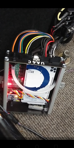
So, the UA4C. It's a standalone with a 22 pin and a 24 pin header on the end for a total of 46 input/output pins. It comes with board-mounted connectors and loose connectors and pins for making up your own harness.

It has 4 ignition outputs and 4 injector outputs so full-sequential is possible in the future. Right now I'll do batch-fire(actually semi-sequential) injectors, 2 at a time. And I'll do wasted spark with that same VW Golf coilpack that Mike used, 2 cylinders fire at a time, one after compression stroke like normal and the other in-between. This is how MANY OE manufacturers did spark since the late 80s until recently. Now they do coil-on-plug which isn't really possible on a VW.

This the same way I've been running since 2008 with my Megajolt. Crank-fire(VR sensor) and wasted spark Ford coilpack. I built that from a kit of parts, and hand-assembled and soldered the through-hole components. This system has been 100% bulletproof so far.

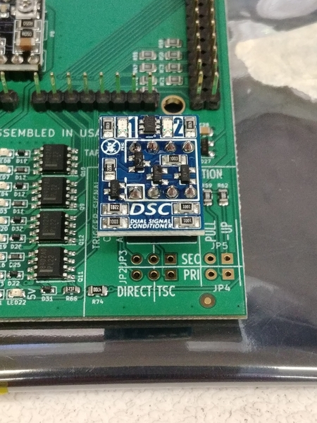
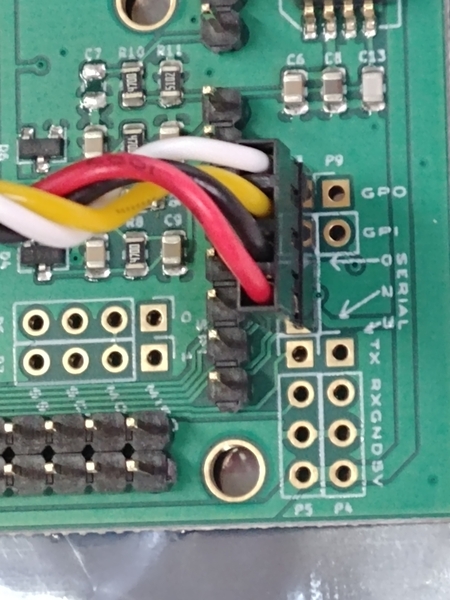
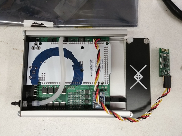
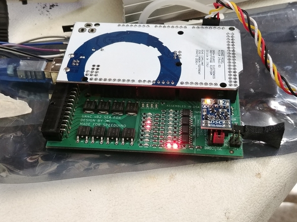
The Speeduino board uses SMT(surface mount technology) and tiny components, so the board is basically finished and pre-soldered when you receive it. I added a bluetooth board for MSDroid(cell phone app to tweak and log on the fly). I added a signal conditioner to enable the VR sensor on my crank to be used as-is. I also added a stepper idle-air valve controller for possible future use(not planning to use at this time, but for $3.50 well-worth it).

The UA4C board includes both an on-board MAP sensor(Manifold Air Pressure or in my case: vacuum) and a barometric sensor for on-the-fly altitude  mixture compensation.

I also got the Arduino Mega that attaches to this board and is the brain of the operation here. And a nice aluminum case and custom pre-cut end plates for the case.

$187 including shipping so far.

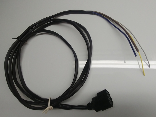
I also ordered a new 3 pin connector from Mario at thedubshop for my existing VR sensor. $13 shipped.

Next up, I'll get some wire in multiple colors to build the harness. I already have extra shielded wire for the VR sensor.

I'm about to order some new injectors and an intake air and temperature sensors from CB Performance. That way they'll surely fit my CB throttle bodies and fuel rails.

Then it will be on to the fuel/regulator/pump stuff and installing a return line through the car.

Stay tuned(LOL!)


2016 Vintage Spyder 2165 type1 EFI/Dry Sumped

Last edited by DannyP
Original Post

Replies sorted oldest to newest

Ha ha ha. 

I already have two CB Performance 48mm ITB(Individual Throttle Body), fuel rails and a TPS(throttle position sensor). I also have an MSD 2225 EFI pump and a Mallory 4305m adjustable regulator. I also have injectors, but they are the old low impedance peak&hold style. I'll buy new high-impedance injectors for this project, they'll actually bolt-on and are compatible with the Speeduino directly.

The throttle bodies are bolt-on, and I can re-use my linkage, air cleaners, air cleaner bases and intake manifolds with zero modification, so that's a big win for easy right there. 

I'll be taking them apart and cleaning the throttle-bodies. I got them from LennyC in a trade a few years ago when he went to Dell carbs and a distributor.

Last edited by DannyP

The ECU and VR connector will both be here on Monday.

I did some calculations, and my engine requires 28 lb./hr. injectors, or 295.31 cc/minute. The fuel pump I have, MSD 2225, flows 43 gallons per hour at 40 psi, and 39 gph at 80 psi. That translates to about 8 or 9 times the required flow, so I'll have way more than enough flow. The specs say 500 hp, but I think more like 300-350hp for that pump, which is still overkill for 170 plus hp.

This is an easy to use calculator for fuel rates and injector sizing:

https://fuelinjectorclinic.com/flow-calculator

I'll be using the Mallory 4305m fuel pressure regulator that I also already have(thanks Lenny!). The fuel pump will be under the tank, and the regulator will be in the engine compartment just after the fuel rail. I'm currently working out connections, returns, and possible surge tank. AN6 fittings will be used at either end. Hard line through the chassis for feed and return to tank.

I found 25 feet each of 11 different-colored automotive wire for a really good price. Chrysler and Ford certified harness wire, in 20 gauge, with insulation that isn't too thick to fit the Speeduino harness connectors:

https://www.crimpzone.com/20-t...oEAQYByABEgJwlPD_BwE

I've decided to keep a running tally each time I spend more on this. And I'm sure to spend more than initially figured. Of course!

Right now I'm at exactly $200.

Last edited by DannyP

Phil, I know you are kidding here.

No, I haven't looked at Jake's stuff, Phil.

The whole point of this for me is to DIY, and to do it with the least expenditure possible. Plus, use components I already have(pump, regulator, throttle bodies, fuel rails). I really enjoy the process of researching, buying, and building it all up. And then running the crap out of it when it's done.

The ECU will be here tomorrow.

@550 Phil check your PMs.

Last edited by DannyP

This is going to be great, Danny.

The sheer betterness of modern EFI and crankfire spark should improve these engines by an order of magnitude compared to an 009 and typical enthusiast-tuned Webers. 

But that's for normal duffers.

Given how close to perfect your particular Webers are maintained, I'll be very interested to hear how much better EFI makes the engine, and how (if at all) you change your spark table to take advantage. 

I received all the electronic stuff last night. It's very nicely made. I'll post pictures tomorrow.

The Spyder needed some attention, which it got this morning. The steering was a bit loose around center the last time I drove it. First thing, found the RF wheel bearing a little loose. Front suspension needed grease also. Then I adjusted the steering box. Ahhhh perfection, as much slop as possible is now gone. What a fun-to-drive car!

Today was 78-80 with a light breeze and sun. My wife and I went for a good old Spyder ride this afternoon, and it was good. Real good.

When I left the house for a ride this morning (about 9am) it was just hitting 67F.

Got back home at around 11am and it was just hitting 77F.  Relatively dry, too.

Gotta love it.

Except for the Ragweed pollen, which makes me sound like Kermit the Frog, as Merklin found out when he called the other day.   My family and neighbors are used to Kermit always being around, but you guys sure aren't.   It's getting so bad I've re-started my allergy shots in a Covid world.  Scary for my age group, but I don't seem to have much choice.  Never had these allergies when I was a kid, but your body chemistry changes over time and I guess mine is getting lazy (like the rest of me).

Last edited by Gordon Nichols

Sorry about your allergies, Gordon, and the heat, Lane.

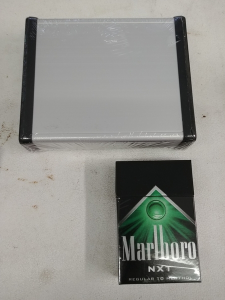
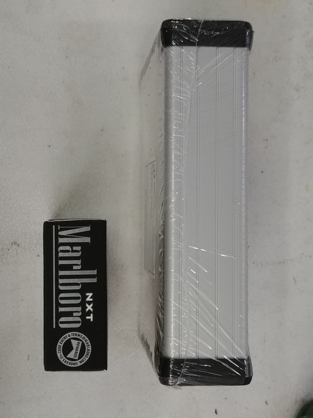
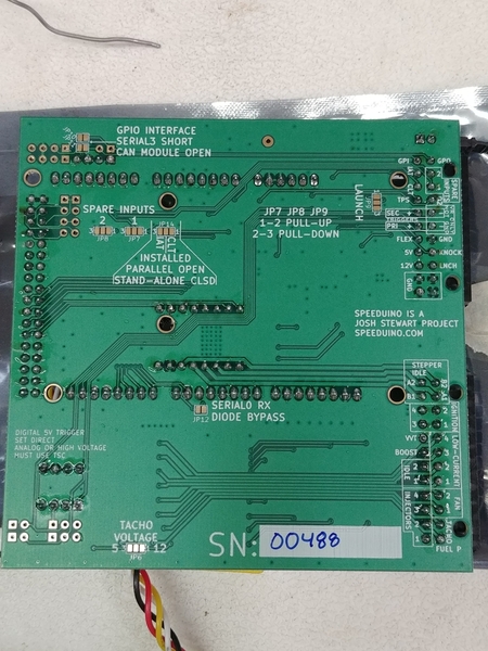
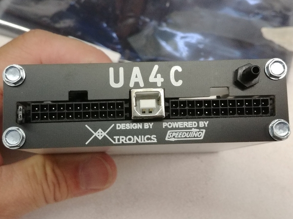
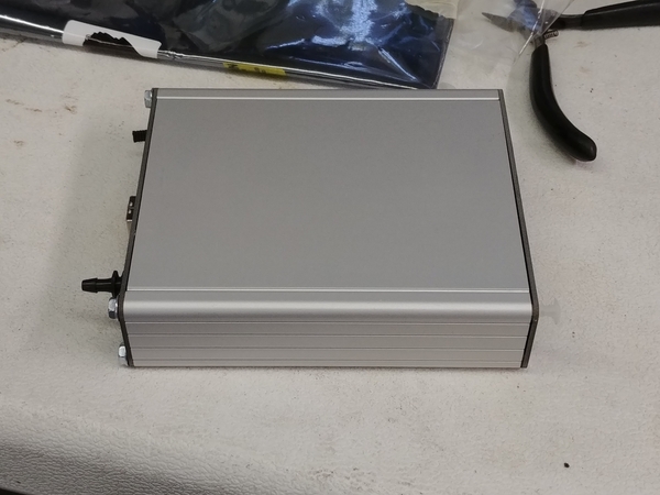
Pictures as promised. First the ECU case, slightly thicker than one pack and longer than two packs of cigarettes. But still, very small as far as an ECU is concerned.20200819_10423420200819_104312

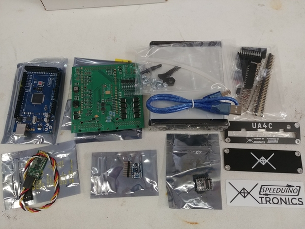
No, I don't smoke people! Here are all the components that came in the box:

20200819_104032

Clockwise from top left: Arduino Mega board, the "brain", the Speeduino UA4C, ECU board that interfaces the car to the brain, a USB cord and the case, connectors, the case endplates(beautiful and copper-clad for interference-blocking), the idle stepper driver, VR conditioner, and finally the bluetooth module.

I've got a bit of soldering to do, and firmware/software downloading. Then some testing and harness-building. This is going to be done over the winter off-season. 

Attachments

Images (3)
  • 20200819_104234
  • 20200819_104312
  • 20200819_104032
Last edited by DannyP

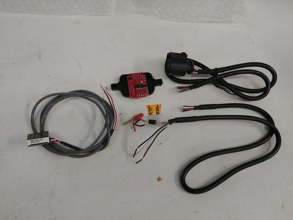
With an aftermarket ECU, you need a wide-band O2 sensor. In order for a wide-band O2 sensor to work, it needs a controller board. Without getting into all the details why, just know that you need to output a signal that varies from 0-5 volts(A narrow-band O2 sensor outputs between 0 and 1 volts and does this without a controller board). The Speeduino can read this voltage and know the A/F ratio and adjust it, this is what's known as "closed loop" A/F control.

A narrow-band can control the idle mixture and cruise mixture, but defaults to open loop when not idling or cruising. That's why it's called narrow-band. Conversely, the wide-band reads all the time and can help with tuning in all modes: warmup, cruise, WOT, decel, etc.

I got the wideband controller, wiring, and a little 3-digit LED display. I may not use the display, I can read the AFR through the app, but for $7.50 why not? 

https://www.wide-band.com/WB-D...nd-Kit-p/wb_d1g1.htm

Once I solder it up and verify function, I'll pot it in epoxy in the little black case that it came with.

$47.50 for that, without Bosch O2 sensor, which I already have from my AEM POS that died. I got this a week ago, but forgot about it. 20200819_103234

@Carlos G : this is wired exactly like yours, diode on the red(+12v) lead, and fuse on the black(ground) side.

Total expenditure to date: $247.50

Attachments

Images (1)
  • 20200819_103234
Last edited by DannyP

Today I spent a couple hours on ECU assembly. I did quite a bit of soldering, thankfully I bought myself a nice temperature-controlled soldering station some years ago.

Those who don't want to read, skip to the pictures at the end. Summation: I did a LOT of soldering today.

I started out with the stepper driver for future idle valve control. It's all surface mount components on a board with 8 pins down each side, so soldering that in is like soldering an old 16 pin integrated circuit.

Then I soldered the connectors for the wiring harness, a 22 pin and a 24 pin. They were easy, the plastic connector snaps right to the board.

Then the rest is all header pins, but a LOT of them. The Arduino Mega has about 80 female contacts.

Then there were a few more for jumpers to select different options, and a 4 pin header for Bluetooth. 20200820_12093820200820_12252720200820_12274620200820_19051920200820_19070120200820_19080420200820_190825

The Bluetooth board will get a heat-shrink on it and probably a dot of hot glue.

It's pretty cool that the board/case came with the vacuum bulkhead fitting and hose for the MAP sensor. It even comes with a 3D-printed plastic piece that keeps the board pushed toward the connector end of the case.

Tomorrow, firmware/software download and testing.

Attachments

Images (7)
  • 20200820_120938
  • 20200820_122527
  • 20200820_122746
  • 20200820_190519
  • 20200820_190701
  • 20200820_190804
  • 20200820_190825

I caught the serial number on your Speeduino board of 488 and remembered the number of our (still dead) Bosch dishwasher when I called in for a service visit:  00042

I wonder if they got stronger after 400 or so?  (The dishwasher, not the Speeduino)

Also, it's good to see someone actually soldering stuff to a circuit board again.  Last time I messed with a PCB was when the SMD power switch detached from my Tom Tom GPS board.  I, too, bought a professional level soldering station (you can find anything on Amazon) with a micro tip and itsy-bitsy solder to get those tiny SMD legs soldered back onto the board, then fab'd a micro bracket to prevent over-pressuring the switch to keep from tearing it off the board again.  

Maybe next you can be on the lookout for a depreciated wave-solder machine or a "Happybuy" reflow oven for SMD stuff - Everyone needs one of those in their shop, ya know?  It would be a lot better than my GE counter-top "Easy-Bake" oven.

https://www.amazon.com/Happybu...6334860728&psc=1

But then, making the fixtures to hold the PCBs and components in place as they get machine-soldered might take longer than the rest of the project!   


Yeah, I've got no need for a reflow oven...........

Today I got a couple things done that were important. First, I downloaded and installed the Speeduino on the Arduino Mega board. Then I tested connectivity with Tunerstudio, check. Next, I downloaded the Speeduino base tune.

No pictures, they wouldn't be showing much anyway.

Tomorrow, I'll attach the Mega to the Speeduino board and test the TPS, O2 sensor, coolant and intake air sensors. I need to download a VR signal simulator, load that into a spare Arduino and test the VR input. 

Once testing is complete, I'll be waiting a while to build the harness and install all this stuff.

Thanks guys. In my post above, I should have said "download and install the Speeduino FIRMWARE on the Arduino Mega". Oops.....

I spent some quality but frustrating time today on the ECU. Got it connected to Tunerstudio ok, but could only test a little. I couldn't get the crank output simulator configured. I also couldn't get the Bluetooth board to pair with either my phone or laptop. I'm sure I will eventually get there, but this stuff is not easy, simple, or foolproof. There is a STEEP learning curve going on, even for me, who understands most of this stuff.

The learning curve leveled out a LOT today.20200824_16172120200824_16172620200824_16173420200824_16171520200824_161709

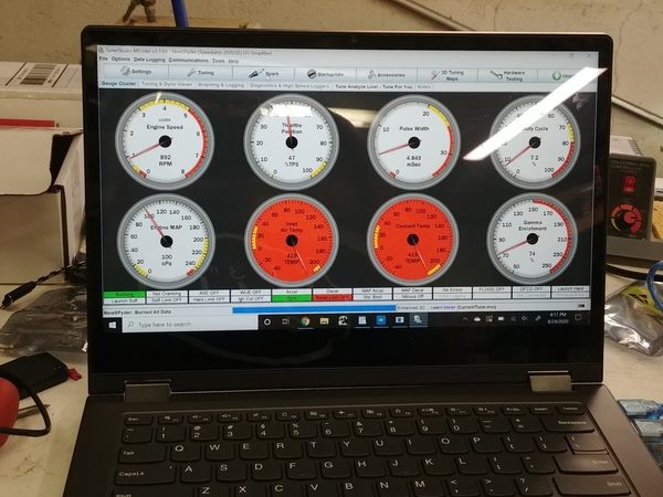
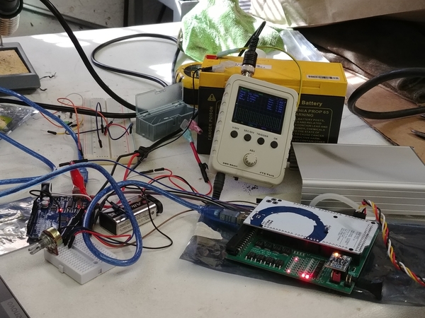
Tunerstudio GUI on top. After I did some initial selecting, all gauges are in range, no more red. Tested MAP sensor with a vacuum pump, and TPS, IAT and CHT with a potentiometer.

Second is Arduino UNO($7) and free software for VR crank signal generator. Download some code and attach a signal and ground wire. Easier now that I know how......

Third is the whole mess with a 12v battery.

Fourth is a little battery-powered oscilloscope. That was a gift from a real tech-geek customer when I installed his FiOS. The guy had a super-fast liquid-cooled computer. You can see the trigger pattern on the scope.

Lastly, the ECU. You can't see the ignition and injection LEDs flashing, but they do. 12v and 5v LED are on, plus tach output and fuel pump output. It's a really nice unit for the money. 

I'm so thankful that I have the option of Autotune. It's well-worth the price. It'll definitely flatten THIS (learning) curve! As in, I won't really have to learn all that much......

Attachments

Images (5)
  • 20200824_161721
  • 20200824_161726
  • 20200824_161734
  • 20200824_161715
  • 20200824_161709

Nothing much to report today. Bluetooth board looks OK, and lights up, but will not pair. I ordered a new Bluetooth board($9 Amazon) plus a usb-serial programmer($11 Amazon) and I'll do it myself! They MIGHT be here tomorrow depending on USPS.

I don't count on anything destined for Friday to actually get delivered anymore.

I soldered up, heat-shrunk and tested the wideband O2 controller and calibrated it.

Total= $298.50

$247.50 + $20 bluetooth stuff and extra Arduino $7(which I had already but will count anyway) + $23.99(Dupont pin crimper for ECU harness)


Bluetooth module was delivered today along with USB-UART serial board to program. Took about ten minutes. The module is now programmed to 115200 baud rate, that is the speed that Tunerstudio and MSDroid use. Even changed the PIN, so it isn't 1234 or 0000 any more.

The first pic is all gauges "clean and green" as we used to say at work.

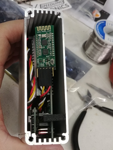
In the second pic the bluetooth module is ty-wrapped on the upper right edge of the ECU in a clear plastic case.

Both my phone and laptop paired up with the ECU quickly, so this project is ready to be installed. The laptop stayed connected 20 feet away, even though the bluetooth antenna is inside the metal ECU case. I'm pretty sure the cover is permanently installed now.

I calibrated Tunerstudio for the wideband controller, and tested the analog O2 input the same way you check the TPS, with 5 volts and ground to the outside pins, and center potentiometer pin to the ECU input. All good.

I also paid for the full version of Tunerstudio at $60.

So we're a bit under $360. Yeah, I could have bought a different ECU, but what would I have learned?

Building an ECU harness and fuel plumbing(fittings and hoses and lines, oh my!) is up next, but it will be a couple months before I start.

20200828_134343[1]20200828_193658[1]

Attachments

Images (2)
  • 20200828_134343[1]
  • 20200828_193658[1]
Last edited by DannyP

And on top of that, you're having a heckuva lot of fun getting it built and running!

Nice clean installation, too.

And what does "Gamma Enrichment" mean for us carburetor users?

Never mind - Just found it:

It's a term that includes warmup, closed loop O2, air density, and baro correction:

http://www.megamanual.com/v22m...l/mfuel.htm#equation

Last edited by Gordon Nichols

Thank you all, gentleman.

I'm going to steal a page from Mike Pickett's book next:

I'm going to install the spark portion first and get that perfect. Then add fuel to the mix. It makes sense to do it that way, especially since I'm already running crankfire/trigger wheel/coilpack.

What's the old adage? One change at a time.

Spark first, fuel later.

I ordered some more stuff:

Amazon:

Bosch coil: $50

Coil connector: $10

Resistor plugs NGK DPR8-EA9 : $11

18 gauge wire(6 colors, 10 ft. each): $12

Crimpzone:

20 gauge wire(11 colors, 25 ft. each): $34

CB Performance:

28 lb. high impedance injectors: $180

IAT sensor: $40

CHT sensor: $40 (these two sensors are more expensive than most, but they're 1/8" pipe thread and smaller)

Fuel injector, sensor, and TPS connectors and injector clips: $55

$450 including taxes and shipping

+$360 already spent

$810 total. All that's left is hose, fittings, lines, and adapters. I'm sure I'll be under $1000.

I'm ahead of the game here, as I don't have to buy a pump, regulator, throttle bodies, injector rails, and crank pulley/trigger wheel/crank sensor. That's gotta be another $800-1000. But still would only be about 2/3rds of CB's complete setup.

Last edited by DannyP

I got some stuff delivered. The coil connector didn't fit, it was for a much smaller VW 4 pin. So I sent it back.

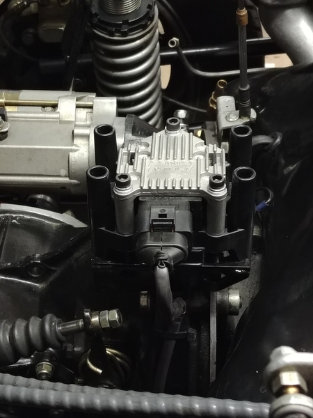
Mike Pickett graciously mailed me an extra he had, that's on the way. Thank you, Mike! The coil is a Bosch and looks exactly like Mike's.

I saved some money on IAT and CHT sensors, I got them both from Ballenger Motorsports for $53 shipped, way cheaper than CB. Plus, they came with pigtails too, so I saved about $60 on sensors and connectors. They are both 1/8" pipe thread, so very small. I got my injectors too, and 4 connectors. I'll post a pic when I install them.

I did some work on the fuel system. I took the fuel rails, injectors, air filter tops and velocity stacks off the throttle bodies. Cleaned up the whole she-bang.

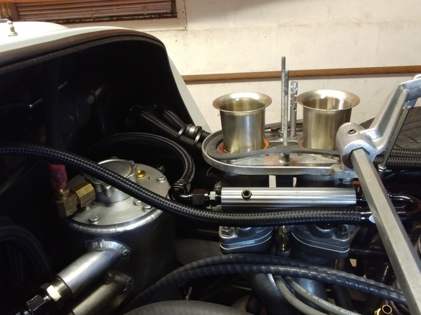
The throttle bodies measure 48mm on the bottom, and 49.5mm on top. The velocity stacks measure 46mm at the bottom. I'm seriously considering making aluminum shims to make them 44 or 45mm throttle bodies, albeit with 48mm throttle plates. If the smallest point is 46mm, there is no need for a bigger hole/passage IMHO. The only thing a larger passage does is lose velocity. I may see how it runs first, this might be a non-issue with injection vs. carbs. The injectors are below the throttle plates. I know that the top of my manifolds are bigger than the bottom of my 44mm carbs, but I didn't measure them.

I decided to use a Subaru fuel filter. All the connections on the pressure side are hose barb(8mm or 5/16") under the tank, so I'll use some Continental EFI hose and those fancy EFI clamps bandied about in that other thread(Jimmy's). The regulator is ready to go and the fuel pump works. Everything on the pressure side in the engine bay and on the entire return side is 6AN. I'm going to drill a hole in the top of the fuel tank and install a 6AN bulkhead fitting. There will be a metal tube inside the tank that returns fuel to the bottom of the tank: no bubbles. I need to run another 5/16" metal hard line down the center. It's 58" long so a 5 footer is perfect. As I found out before, 5/16" fuel line is good for 350hp.

Currently working on plumbing/hose/fittings parts list. I'll be starting this in mid-October.20200913_185425[1]20200913_185446[1]20200913_185514[1]20200913_185843[1]

Attachments

Images (4)
  • 20200913_185425[1]
  • 20200913_185446[1]
  • 20200913_185514[1]
  • 20200913_185843[1]

Finally starting on the actual build, after all the parts and pieces have been gathered.

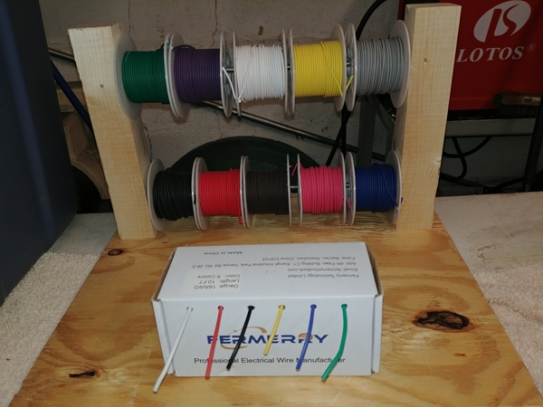
@Alan Merklin it's funny you posted about the wire storehouse. Wire came in loose bundles. I found these reels on Amazon for a few bucks. I made this rack yesterday:20210126_113129

30 feet each of 10 colors of 22 gauge.

10 feet each of 18 gauge in 6 colors.

Well at least I'm starting it. I'm doing spark only first then will add the fuel after I get it to run on carbs. I think it's a good plan.

Attachments

Images (1)
  • 20210126_113129
Last edited by DannyP

I just realized I never finished my parts list and costs.

I was at $810, but saved $60 by buying the CHT and IAT sensors from Ballenger Motorsports, so we're at $750.

I spent $210 on Amazon back in October for Gates Barricade EFI hose, clamps, fittings, adapters, some AN braided hose and fittings for the engine compartment, a fuel pump clamp, and even an adjustable aluminum AN wrench.

I spent another $40 at Advanced Auto getting some copper/steel fuel lines for feed and return through the tunnel.

I may have spent a few more dollars at Jegs or Summit buying a bulkhead fitting and teflon washers for the fuel return fitting in the tank.

I'm right around $1000, like I figured, except for the sweat. I've decided to go for idle speed control via  a stepper valve, so that valve and housing and vacuum hose will get added when I figure it out. I'll be using the built-in ports in the CB throttle bodies to add a "calibrated air leak" to control idle speed.

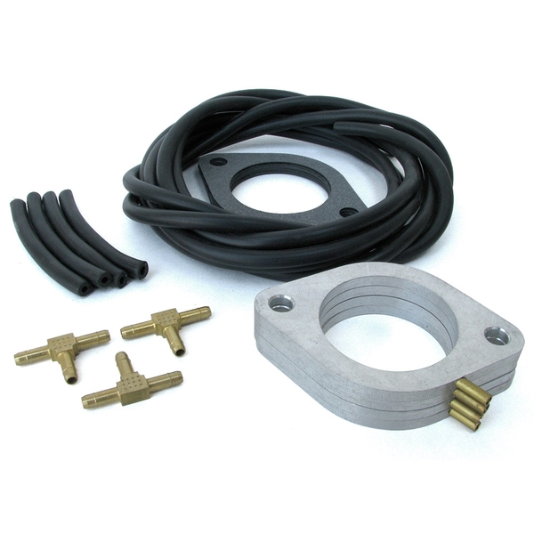
SpyderMike from the spyderclub.com most graciously(BIG THANK YOU!) sent me his CB vacuum reference kit. This installs a spacer under each throttle body with a small brass fitting to allow all 4 intakes to couple together. This hose gets routed to the ECU's onboard MAP(manifold air pressure) sensor. I'm hoping to hide the vacuum hose under the fan shroud.

vacuum kit

I spent some time today laying out the wiring on paper. I've got 28 wires to route to and from the ECU. Some are already there: power, ground, ignition, tach, three fused relays, and four wires to the fuel pump up front. For the fuel pump I'm stealing my trailer light harness that ran through the car when I flat-towed.

I've got to make a new coil mount for the Bosch "smart coil" to replace the "dumb" one from the Ford Escort(Megajolt).

I'm running new wires to the VR crank sensor, CHT, IAT, TPS, coil and injectors. That should keep me busy for a while...

Attachments

Images (1)
  • vacuum kit
Last edited by DannyP

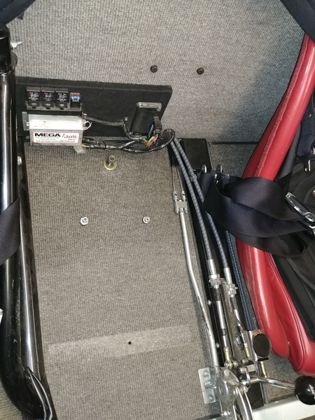
I removed all the Megajolt bits and wiring. I also ordered a 6 fuse power and ground distribution block for $15 delivered, should be here tomorrow. It's 3.5" square, so it should fit nicely on my back board.20210130_141844

I'm reusing my old relay board, it's from a 1990 Subaru. Very thin and compact for 3 30 amp relays.

The wires coming through by the shift cables are the Vintage harness. Black is switched ignition, orange to the tachometer, light and dark green to the GM oil temp sender, and purple to the oil pressure idiot light. The last three have nothing to do with the EFI, but the harness needs to be inside the cockpit. I'll heat shrink and tuck them under the board.

I'll connect the ground bus to the steel center tunnel and run an always hot lead to power it all.

I also found a Chrysler idle air control(IAC) stepper motor and wire pigtail for $10 on eBay. I'll make a manifold out of a hunk of aluminum and put a tiny breather filter on it.

$1025 so far.

Forward progress.

Attachments

Images (1)
  • 20210130_141844

Chrysler IAC showed up, so I'm off to the metal place today to see if I can get a 2" x 2" aluminum chunk for the IAC manifold.

The fuse panel showed up too so I've mounted that and am starting the wiring(and recording the colors and gauges for a schematic). I ran an 8 gauge(already had) feed to a 40 amp circuit breaker($5), to a couple relays(already had), then to the fuse panel. 8 gauge ground buss next then the small and tedious wiring begins.

I used my new ratchet Molex crimper for the 3 pins on the VR sensor, that thing is SWEET and well-worth the $23 price. Shielded cable is a MUST on VR sensors. One heat shrink later and it looks perfect.

I bought a later VW Beetle plug wire set($37) and proceeded to cut the coil ends off. I made up and 8mm silicone wire set using the Ford Escort wires with the VW coil ends. A little silicone spray and they went together nicely. The Ford wires are the perfect length when the coil is mounted near the transmission, and the plug boots are a perfect snap fit on the plugs and with the Bosch air seals.

$1067 so far. These projects all have price creep, don't they?

Pictures later, I promise.

As promised, I have some photos. Didn't get that much done today, had to deal with a repair shop that couldn't get the OBD plug to work for a yearly emissions inspection on Michelle's Subaru. There was nothing wrong with it. Of course.

20210204_181607

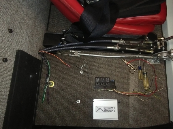
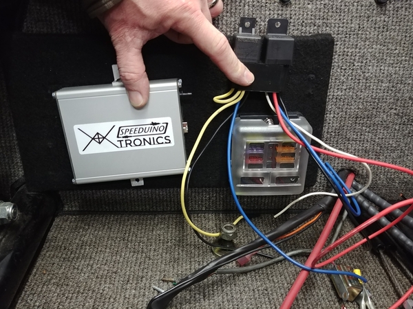
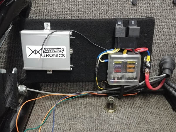
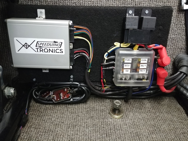
I didn't want to Velcro or tape the ECU to the board. Not a big deal to cut a couple small pieces of aluminum angle for mounting. The 6-32 screws had to be cut very short to not interfere with the board. Good size comparison of the small ECU.20210204_194241

Hybrid Ford Escort 8mm silicone wires with VW New Beetle coil ends and old Beetle Bosch airseals.

20210204_204256

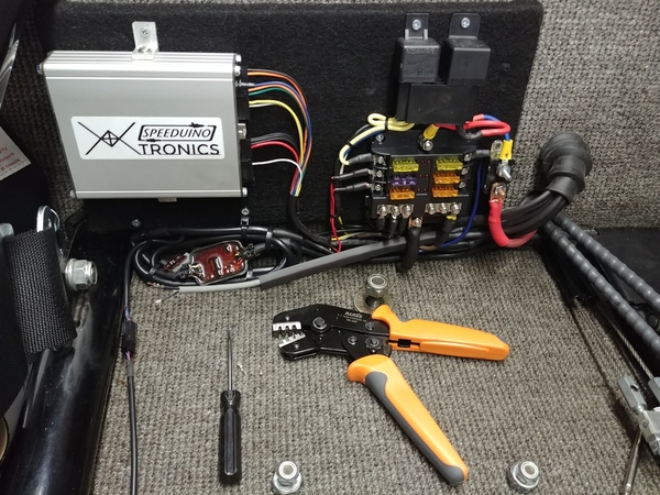
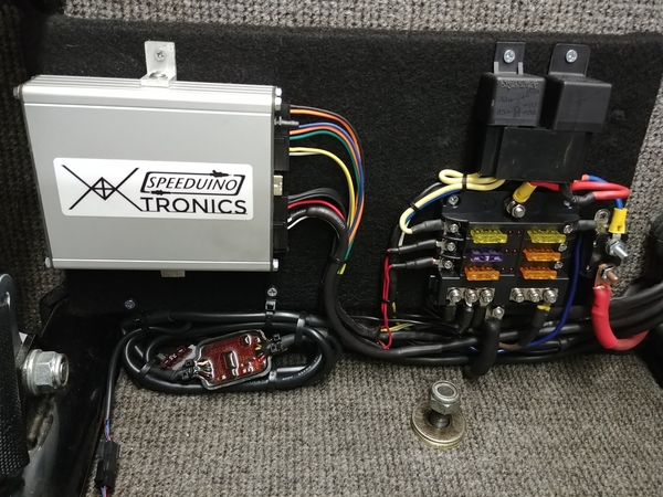
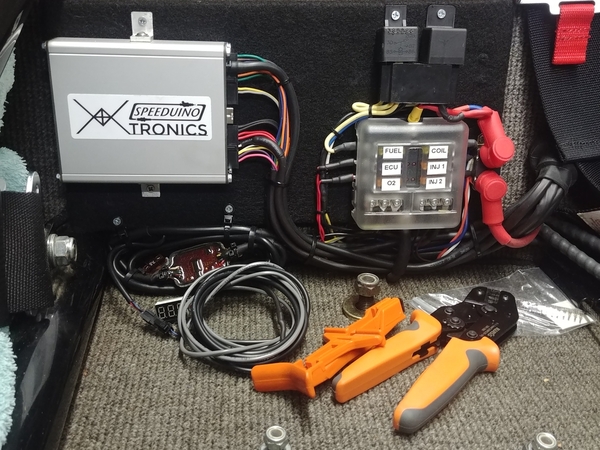
Decided to scrap the Subaru relay panel. I'm using a 40 amp circuit breaker on the main feed, a 40 amp Bosch-style main relay. Then another 30 amp for the fuel pump. The 6 fuse panel distributes power to the ECU, O2 sensor, coil, pump, and injectors. It'll lay out like this pic above eventually.20210204_204737

Waiting on some 6 x 70mm bolts to mount the coil. Thankfully I don't have to re-make the mount, it's welded to the transmission strap.

Tomorrow, some serious wiring. Maybe I'll fire it up on Speeduino ignition and carbs soon.

Attachments

Images (4)
  • 20210204_181607
  • 20210204_194241
  • 20210204_204256
  • 20210204_204737
Last edited by DannyP

I did some more work today. It's coming along nicely.20210206_141428

This is the ground attachment for the whole system. Crimped the ends with a big hex crimper with multiple dies. Then marine heatshrink and star washers under bolts. You can see the brake, clutch and fuel lines in the 1" high tunnel.

20210203_100012

This crimper, cutter, and ends was $30 on Amazon.

20210206_141453

Greg makes custom fiberglass covers for between the seats. Finishes it off nicely. I cut a small slot in the lower left corner.

20210206_183437

The EFI feed is closest to the camera.

20210206_183454

It runs down the left frame rail then acrid the firewall toward the center. You can also see my VR sensor wire. It is grey 2-conductor with shield. You can also see the firewall grommet.

Attachments

Images (5)
  • 20210206_141428
  • 20210203_100012
  • 20210206_141453
  • 20210206_183437
  • 20210206_183454

More:20210206_183630

The other side of the firewall grommet and 40 amp system circuit breaker.

20210206_183621

All that power and ground stuff is done. Main and fuel pump relays are done. Tomorrow I'll move on to ECU connections. Once I power the coil and terminate the VR crank sensor and tachometer at the ECU I can fire it up.

I tested my work so far, and no smoke was released or fuses blown LOL!

I have some boots on the way to cover the circuit breaker studs.

I'm really pleased with the way it's coming out. That little fuse panel is sweet too.

Attachments

Images (2)
  • 20210206_183630
  • 20210206_183621
Last edited by DannyP

Good evening. I did a lot of wiring today. It took a long time to make and run the coil harness. Four wires: power, ground, and two small wires to control the two smart coil drivers in the pack.

I am sleeving as much of the harness as I can in heatshrink. I bought it in 8 foot rolls, but you can only get a couple feet to slide over at a time.20210207_122423

That's the only picture I took today. I also installed the wideband O2 sensor and ran that wire toward the ECU.

Pretty much all the wiring has been run except for injectors, TPS, head temp and intake air temp. That will come later when I do the fuel portion.

Michelle was a valuable help fishing the wires through the firewall grommet, which is now curved and impossible LOL.

Tomorrow I'll work hard on terminating the ECU wiring, then maybe fire up on spark and carbs.

Attachments

Images (1)
  • 20210207_122423
Last edited by DannyP

What we need is a pause every so often, and then get a synopsis of what's been going on by Pintel and Ragetti, those two wayward pirates from the Caribbean with a knack for getting to the heart of things:

Pintel and Ragetti

"Well, he started out with a perfectly good, running car but desired a bit more, so he decided to go whole hog on a computer-controlled engine management system, but he wanted to do it in steps so he started with deciding on what major parts to use and ordered some and got others from local junk yards.  Then he worked on the wiring for everything and had to buy a few tools (he loves tools and has a lot of 'em) to complete some of the larger connections.  

"Meanwhile, some of his parts began to arrive (even though deliveries are delayed by the Pandemic) and he could begin to piece together the fuel system and make necessary modifications to major parts.  The wiring has been progressing while he has made the harnesses in the car, many of which are always visible, as neat as possible and added lots of fuses and circuit breakers for added safety and to prevent the loss of wire smoke from the Lucas parts.

About those British, "Lucas parts", most recently, he has conducted the "Lord Lucas, Prince of Darkness" test for his combined British, Teutonic and Middle Earth electricals and found that no powered smoke escaped, so he will soon be testing the ignition side of the project by "Releasing the Kraken"........  
Oh,  Sorry....   No Kraken just yet....  
But he will be starting the engine with the new Engine Control Unit (ECU) and, once that is successfully done he can move on to installing the fuel delivery system and checking for more smoke.

Come back again, soon, as we discover more things to tell ye!"   -   Pintel and Ragetti

Last edited by Gordon Nichols

I got a lot done today. I was happily wiring away when my coil bolts came in the mail.

So I took a break from wiring. I drilled and tapped the three holes. I had to put some ALB lightening holes in my bracket(but only for bolt clearance), there is a piece of steel angled under the flat part the coil bolts to. A bit of masking and paint and:

20210208_165356

Then back to the wirework.

20210208_190704

I tied up the O2 sensor wiring under the ECU, that came out a couple feet long. It's OK for now. Those Amazon crimpers are totally awesome. After over a dozen perfect crimps, I'm sold. I pull-tested every one. I don't think I'll ever solder another Molex pin again(that's how I did the Megajolt harness in 2008).

20210208_190722

The fuse box is all done except for the injector harnesses, one for each side of the motor. Driver's side will also have the TPS. Passenger side will have the wires for head and intake air temperature sensors.

20210208_202533

And all done for today. I powered it up, seems OK. Main relay clicks, then the fuel pump relay clicks on for 6 seconds to pressurise the system. O2 controller powers up and reads 19.0(no fuel i.e. full lean).

Tomorrow I'll get the laptop out and start testing. I'll pull the plugs and spin it over, checking for crank signal. Then I'll throw a timing light on it and verify a fixed(10 degree) value.

If that checks out, new plugs in and FIRE it UP! Maybe load a spark curve first LOL?

Attachments

Images (5)
  • 20210208_165356
  • 20210208_190622
  • 20210208_190704
  • 20210208_190722
  • 20210208_202533
Last edited by DannyP

What's the little potted thing under the Speeduino box?

Yup...  Crimped Molex terminations are the way to go.  Properly done, they make a stellar connection and with a hand-held crimper you can work almost anywhere.  

We didn't have Amazon as a go-to when I was working so we bought the crimpers (both hand held and bench) from Molex for astounding $$$$$$$. The hand-held equivalent of the one you show (very similar to mine) was a shade under $300 bucks!  (and how do you spell "Rip-Off?"

Nice progress there, Dan.  Your thing of beauty is becoming more beauteous, inside and out.

The little potted thing is my wideband O2 controller. I thought I had posted pics, but I guess not.20200826_12153120200831_12375020200831_161615

The wires are really long. I can shorten them later.

Yeah I couldn't justify $300 crimpers. $23 knock-off, absolutely.

Thanks Gordon.

More later, I should be testing for spark.  It's snowing so I'll be in the garage today.

Attachments

Images (3)
  • 20200826_121531
  • 20200831_123750
  • 20200831_161615
Last edited by DannyP

Ah....   I see you're using the lab potting technique we used on cables in the 1980's.  We had forms for some of them but others, especially for pre-production quantities, we did free-form with masking tape - worked great.  You really can't beat submersion potting for anything in a hostile environment (and your car, at any speed, in rain, qualifies as a hostile environment).  

Snow's just starting here at 10am.  Another 6" due here in the snow belt of central Mass.     We're sitting somewhere around 2'+ on the level after compaction.  I'll be working inside where it's warm.  Just checked to see if the velcro adhesive on my heater controller stuck after I heated it up before applying.

It's still sitting there, stuck under the radio.  

Life is Good

Attachments

Images (1)
  • Life is Good

20210209_134422_HDR

That is a very clean 36-1 toothed wheel signal. I loaded up a 16 x 16 version of my 10 x 10 Megajolt spark table.

Tunerstudio has some really cool features. It has interpolation. Put a value on either end of a row or column in any table, highlight, click interpolate, and all the cells in between the two fill in equally. Sweet.

Tomorrow I'll be firing it up hopefully.

Attachments

Images (1)
  • 20210209_134422_HDR

Thanks, Martin.

I know it's been a few days since I posted. I hooked everything up and thought I was ready to fire it up on spark only. That seems to be the hardest hurdle for almost every install.

There is an option in spark setup for output either "going high" or "going low". It depends on which coil you use, most are "going low". This didn't make too much sense to me, but going low has no voltage on the output, goes "high" for a couple milliseconds(which is the dwell time) to charge the coil, then goes low to fire the coil. Special thanks to Mike Pickett for the assist!

Tunerstudio is set going high initially which leaves 5v on the output basically all the time the key is on, except when the coil fires. The output goes low to charge, turn goes back high to fire. The problem with this is that coils burn out, just like in the old days with key left on and points closed.

20210210_133035

Oops! New coil from NAPA, $90 with tax. Ouch. I could have waited for $60 shipped but... This little option in spark setup is obviously crucial. The good news is the coil driver, the smart part, is OK and I'll save it in the tool/spares bag in the car. It simply unsnaps from the coil. You can just see it on the left.

The Lucas Druid Gods should be happy 😊. I let out some sacred smoke from the coil. It got HOT and smelled funny! Nothing else was harmed, thank goodness.

I changed the setting in Tunerstudio and mounted the new coil. I tested the coil outputs both by watching the ECU LEDs flash and hooking the outputs to my mini-oscilloscope. Good to go. Then tested at the coil connector, OK. Removed coil driver and tested the driver output, and good once more. Final test, hook it all up and test at the wires with an inductive timing light. And good, ready to start!

Fuel pump fuse in, fill the bowls, a few pump squirts, and success! It runs!

I also have video of my AFR at 14.5, sliding down(richer) to 13.5 when fully warmed up. On carbs. You CAN get them lean and running well on carburetors.

I have some short video but get errors when uploading even though the files are only 10mb mp4. I took a couple screenshots instead.Screenshot_2021-02-13-09-42-01Screenshot_2021-02-13-09-41-36

Attachments

Images (3)
  • Screenshot_2021-02-13-09-42-01
  • Screenshot_2021-02-13-09-41-36
  • 20210210_133035
Last edited by DannyP

Once it was warmed up and idling smoothly I got the timing light out again and verified that TDC was EXACTLY TDC.

I was a few degrees off, but that is easy to change the timing offset with a couple clicks in the software. You can set it anywhere between 0 and 360 degrees of offset. It was set for EDIS at 90 degrees and I ended up at 95. No more timing light, ever. I hope. It's really difficult on a Spyder. I tape an inspection mirror on the end at a 45 degree angle, coming in from the driver's side(don't touch the cylinder 2 J-tube!).

Anyway, now that it runs I can move on to the fuel portion.

No. Not OBD. No emission testing either. There is a USB connector on the ECU which I used for initial setup and testing.

But then I did purchase, program and install a Bluetooth transceiver. It cost about $10, and is I link up with either my laptop and Tunerstudio OR my phone with MSDroid(MegaSquirt Droid) app for on the go access and changes. I can store and load multiple tunes that way.

I took a couple days off, but now I'm back at it. Here's a picture just for @IaM-Ray:

20210215_185916

All covered up. I've got to add about a dozen more wires for the injectors, temp sensors, TPS, and stepper idle control. That will get done soon.

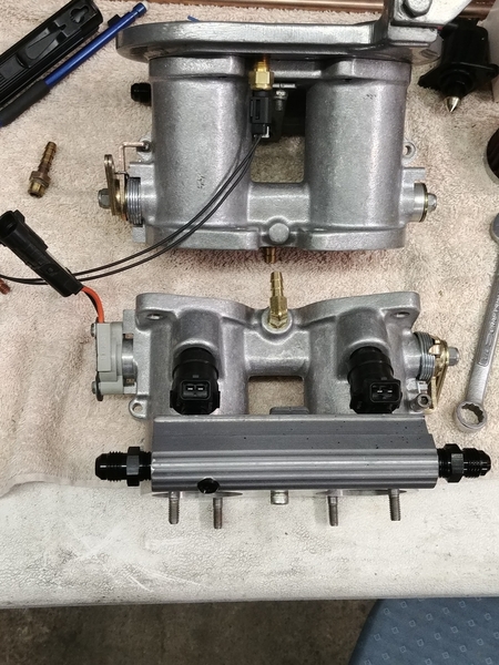
I've started the plumbing with the injectors and rails on the throttle bodies. After some looking around I decided to use good old Permatex case sealer on the threaded fittings as it is gasoline, oil, and alcohol proof. There were quite a few recommends on H.A.M.B. so good enough for me.

I like black fittings. I never liked the red and blue that a lot of people use. I even found some nice black anodized Allen-key pipe plugs.

I decided to install the IAT(intake air temp) sensor into the air filter base for a cleaner look. Electrical harness time tomorrow.

20210214_181844

Time to unbolt the carbs and start the fuel system.

Attachments

Images (2)
  • 20210215_185916
  • 20210214_181844
@DannyP posted:

No. Not OBD. No emission testing either. There is a USB connector on the ECU which I used for initial setup and testing.

But then I did purchase, program and install a Bluetooth transceiver. It cost about $10, and is I link up with either my laptop and Tunerstudio OR my phone with MSDroid(MegaSquirt Droid) app for on the go access and changes. I can store and load multiple tunes that way.

That, sir, is slick AF

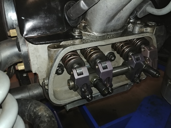
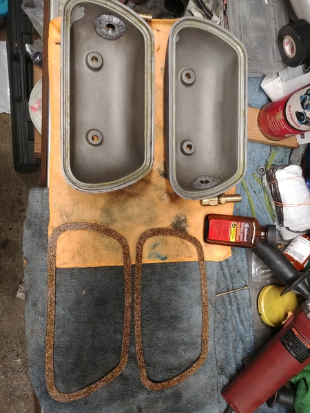
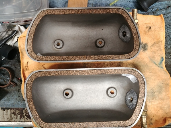
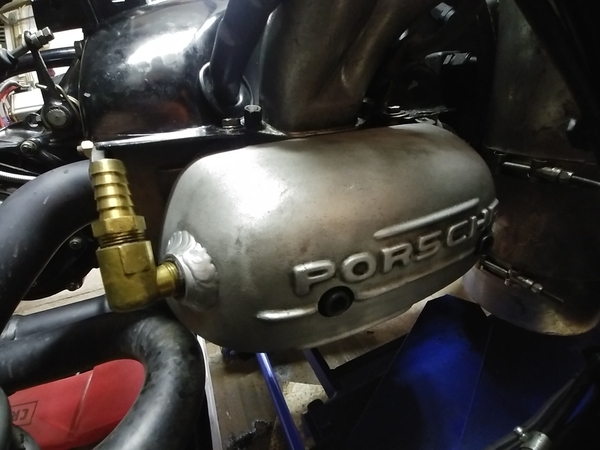
The last couple times I fired the car up I noticed the valves were a little noisier than usual. I figured I'd post this even though it isn't specific to EFI. But it'll run better either way.20210217_16492120210217_16423420210217_17001420210217_172924

Those are Pauter 1.5 rockers from 2002. They have roller tips and roller bearings and they used to be bright purple-anodized. I had a couple that were a tiny bit too loose.

The contact cement on the valve covers cleans up with a rag and a couple squirts of carb cleaner. The glue literally slides right off. It took me twenty minutes to do the whole job, plus ten minutes for the glue to tack. Thin layer on the cover and the gasket, wait, and stick. I grease the gasket on the head side.

Look at the first photo, notice how there is basically no oil in the head? Dry sump, my friends. That huge pump sucks the oil out immediately. There is plenty of oil on all the moving parts and friction surfaces. It just gets evacuated and doesn't have a chance to pool and leak.

I really need to get my exhaust ceramic-coated.

We're getting about 6 inches of snow tomorrow so I'm sure to be in the garage working on the EFI.

Attachments

Images (4)
  • 20210217_164921
  • 20210217_164234
  • 20210217_170014
  • 20210217_172924

No pictures to go with today's summary, sorry.

I removed every bit of the old fuel system, except the carbs(only 8 bolts). Besides, the carbs protect the intakes from stuff getting dropped in there.

I pulled a line off one carb and ran the fuel pump until the tank was empty, I had about 5 gallons in there. The snow blower, BMW bike, and gas can are all filled up with Ultra 93 now. Yes, it was treated with Stabil.

Fuel tank is out, hose, filter, pump, hard line down the middle to a threaded brass T, and hard lines across and up the firewall to just in front of each carb. I also pulled the tunnel covers and the cable shifter over the tunnel. The cable shifter is bolted to a U-shaped steel piece about 1.5 feet long. It looks like I only need to drill one hole in the front and one at the firewall to accommodate the return line.

I'll start installing new stuff tomorrow.

When you emptied your tank with the fuel pump, how much fuel was left in the tank?

I'm just wondering if the placement of the fuel tank exit is in the correct location to use all of the fuel in the tank or not. I'm wanting to do what Ed did and remove the "bump" in the fiberglass that interferes with my foot while using the gas pedal. It's supposed to be there for clearance of the fuel tank exit.

Probably a gallon or so. I agree it isn't in the best spot for a Spyder. Since the tank is angled forward fuel is in the front when the pickup is uphill near the back.

I was thinking about moving the bung to the front until I thought about it. Under acceleration fuel goes to the back. I've never had a starvation problem, probably due to the float bowls but I don't want to chance it. And I don't want to run a swirl pot either.

What we really need is a custom tank with a small well and baffles that also looks the part.

Put two 5-hole sender flanges on it. One for the wrong fill location and one for the correct. One tank to fit them all.

Last edited by DannyP

But why?

A custom tank has been on my short-list for years-- but the intent is to use the real-estate an IM has behind the beam (assuming one has such a thing, and I do) to get the fuel lower in the chassis and open up some more trunk space.

I understand that this is mostly just a project for me, as are most such things. A custom Spyder tank would pay for itself after about 1000 cars, assuming every car they went into was for somebody as passionate as Danny or Carlos or Ed. I can tell you with 100% certainty that not many people are.

I have found that when I'm building custom things, it's best to just assume you're going to be making one, and not 100 of the thing, and proceed accordingly.

True except when I did the research for my IM to make a new tank IM made a wooden test box and I found the custom tank maker and 10 units was the magic number.  The. I found out about the existence of a larger filler pipe and cap and had one sent to me after the build .   Just saying

After all of this I found out I could have done the tank in injection molded material for the same cost with even more fireproofing that an all aluminum unit

@edsnova posted:

You will find—and I guess you already have found—the pump, filters and lines are dead simple. I'm very keen to see how your electronics go.

The physical wiring and stuff isn't hard, nor is the plumbing. A bit tedious perhaps, but not hard. The planning of plumbing and wiring paths is where most of the effort goes, at least for me.

It's gonna be the maps and tables and LEARNING what does what and how and why.

The cool thing is there are some very knowledgeable and helpful folks on the Speeduino forum, plus I email(pester) Mike from time to time.

@DannyP posted:

I'm not doing anything more difficult than Mike Pickett already did. He pushed me over the edge, just like my friend Stan "Dry Sump" Galat.

I will say the learning curve is steep on this EFI stuff, and Mike already had a bunch of experience compared to my zero experience.

Repeat after me, "It's dry sump, it's dry sump, it's dry sump. I know I know I'm being a bit sophomoric. I can't help it sometimes.

@Robert M I don't know if you were being humorous or not, but honestly I didn't ever notice how dry my heads were in the rocker area before.

I've started to work on the fuel system. First I had to move one of my horns to the driver's side, the other was already there. Then I had to move the gas heater fuel pump to the front of the beam. The cool thing is that the 4 beam mounting holes are unused in a Spyder, making useful mounting areas.

20210220_155356

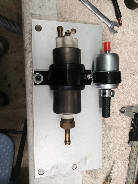
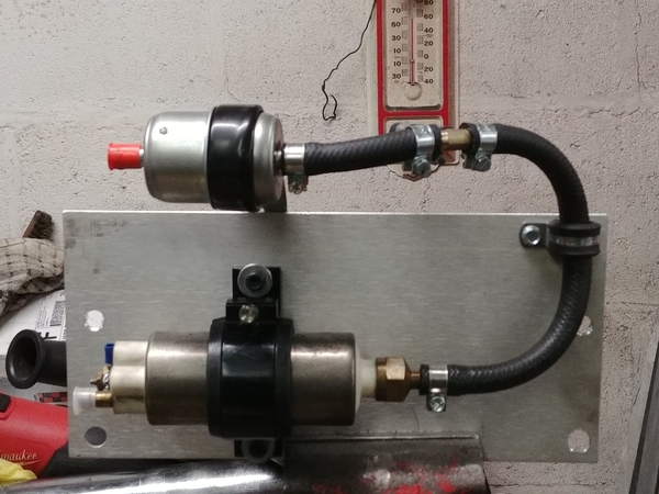
I cut a stainless strap/mount for the Suby after pump fuel filter, which will mount just in front of the beam. I then mounted a pre-filter and the pump to a 3/32" aluminum piece. That will mount to bottom beam tube with a couple muffler clamps.

Attachments

Images (1)
  • 20210220_155356
Last edited by DannyP
@DannyP posted:

@Robert M I don't know if you were being humorous or not, but honestly I didn't ever notice how dry my heads were in the rocker area before.

I've started to work on the fuel system. First I had to move one of my horns to the driver's side, the other was already there. Then I had to move the gas heater fuel pump to the front of the beam. The cool thing is that the 4 beam mounting holes are unused in a Spyder, making useful mounting areas.

I cut a stainless strap/mount for the Suby after pump fuel filter, which will mount just in front of the beam. I then mounted a pre-filter and the pump to a 3/32" aluminum piece. That will mount to bottom beam tube with a couple muffler clamps.

I was goofing along the lines of something that rhymes with dry sump that a lot of male teenagers experienced growing up. Hence my comment about being a bit juvenile.

I worked on the fueling system more today.20210221_14331420210221_17093120210221_17101920210221_171152

I installed the hard lines through the chassis. They are 5/16" copper fuel/brake lines from Advance Auto. I used rubber grommets in the back by the firewall. I put some heavy heatshrink where the lines go through the cockpit bulkhead and the front firewall. The shifter and center covers are all put back in now.

Back by the engine I installed brass 90 adapters, and aluminum AN-6 adapters. All set for braided hose to the fuel rails.

There really isn't as much room in the beam area as in a Speedster. The master cylinder just clears the lower tube. I had to put the post-pump filter in front of the beam due to the gas heater exhaust.

I'm waiting on the CB fuel injection T for the bottom of the tank. I've decided not to drill another hole in the tank for the return.

I removed the carbs and linkage, then started the throttle body installation. Of course the intake manifold studs are a little short, I have some longer ones to install tomorrow.20210221_172707

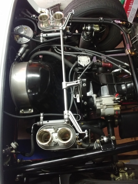
The throttle bodies (roughly 48-49mm) are a port match to the manifolds. I think they look good on the manifolds.

Tomorrow I'll swap the studs and run some braided fuel hose, including the pressure regulator. Then I can finish the wiring and vacuum hose.

Attachments

Images (5)
  • 20210221_143314
  • 20210221_170931
  • 20210221_171019
  • 20210221_171152
  • 20210221_172707

Thanks, Martin, I appreciate that.

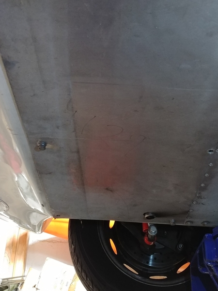
Gordon, the Webasto is under the dash and mounted through the fiberglass firewall. The exhaust goes forward under the tank then down just behind the beam on the passenger side. It sticks down about 1/2" from the aluminum under-pan. I have heatshield sleeves on the corrugated stainless pipe as well as stick-on heat shielding on the top of the footwell and the bottom of the steel tank. It has worked flawlessly for the last three years.

I'll post up some pictures later on to illustrate, but you can just see the pipe in the third phot in my previous post. Look all the way on the right side in the background.

Last edited by DannyP

OK, now that I know what to look for, I found it.   Mine is a bit less inconspicuous     but you really have to look way under the car to see anything.  I also had the advantage of a straight shot, once past the 90º elbow going straight up into the heater, so I could use just a rigid length of exhaust pipe out in the open with no need for insulation.  I think I anchored the far end to one of the front bumper mounts.

I ran mine out to the passenger side because the heater air inlet is on the driver's side, right behind the headlight bucket, with a shelf installed for protection.  Using a left/right air cross flow keeps any combustion exhaust from finding the air inlet.  

Gordon, my heater exhaust cannot be seen. It runs inside the beam and protrudes from the aluminum undertray about a 1/2". The exit is the only part that can be seen. The exhaust exits right into the slipstream of air under the car. The combustion intake air is from up by the fuel tank and has a muffler on it. The muffler came with it and quiets the "roar" a good amount.

My cabin/heated air intake is from inside the driver's rocker panel, that way I don't have a heat loop. I still don't have a top so it doesn't really matter where that air comes from as long as the intake air doesn't warm too much(like if I had a top!) the heater never shuts off.

Last edited by DannyP

Moving on to today's work...

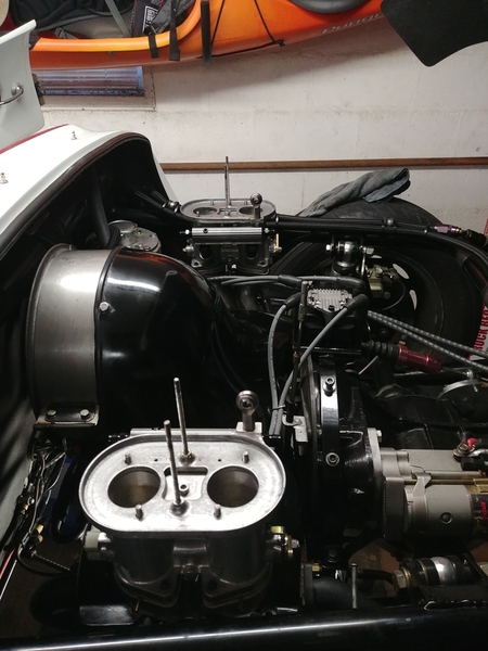
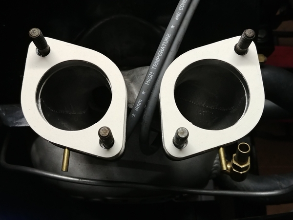
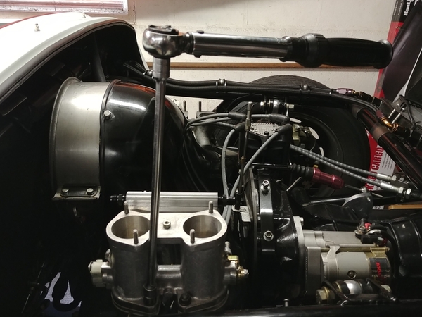
I first removed the old and then installed longer studs so I could mount the vacuum adapters and the throttle bodies. Torqued them to 18 ft. lbs.20210222_13510520210222_135718

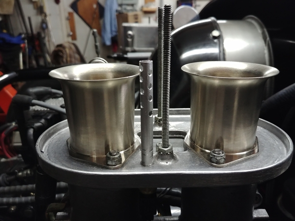
Then I moved on to linkage and the IAT(intake air temp) sensor. That was a fun bit of fabrication. I took a water temp sensor and hid it under the air filter base. Then used an aluminum acid brush to extend the sensor. I drilled some ALB holes in it, not for lightness, but for heat transfer. I used a little JB Weld and crimped the tube in place on the sensor. It should read the air passing into the stacks.20210222_19382220210222_19382920210222_201201

It's a standard GM sensor, the calibration is already in Tunerstudio. No big deal if it's not, you need three temperatures and resistance readings.

After that I moved on to the crossbar linkage. I had purchased new downlinks a while back so installed that.20210222_215444

It snowed today. Again. I got a lot done, even if it doesn't really look like it.

I guess tomorrow I'll get to the plumbing and wiring LOL!

Attachments

Images (6)
  • 20210222_135105
  • 20210222_135718
  • 20210222_193822
  • 20210222_193829
  • 20210222_201201
  • 20210222_215444

Danny, I think anyone who does anything mechanical in their garage knows you had a very productive day. Everything takes longer than originally planned so to achieve multiple tasks, AND carry on with normal (albeit COVID) non-car life, is good going. Regardless of skill level, it’s always a good feeling of self-satisfaction when one gets to the end of the day and good progress has been made. It provides good motivation for the next day. And documenting builds on here provides inspiration and motivation to the rest of us. :-)

Just to set the record straight, THIS is my coffee maker:

IMG_7275

And since this is the first major stupid annoying off-topic thread drift to defile Danny's excellent and relevant EFI DIY tutorial, I'll tell its story as well.

I make about two-three pots per week of Eight O'Clock coffee in this. I actually put some of the hazelnut variety in there last week for a change of pace—first time ever. I store the result in a sealed thermos carafe, and microwave as needed after the second day.

About once a year I run white vinegar through it to clean. I have owned it since 1999.

And where did I obtain such a fine precision machine, you may ask.

It was my dear mother's—or, more accurately, it belonged to the previous owner of my dear mother's townhouse. Mom didn't want it, so when she moved into her new place, I took it. It lived in the basement of my Hartford home for a few years, unloved (ne' undiscovered) while I ran to ground my 1990s interest in grinding my own beans, importing brews from the Kona coast, etc.

I placed it back in service on my move to Baltimore City in 2003, and have enjoyed its fruits ever since.

I have not modified it in any way.

It has no foot pedal, nor variable speed. It will not accept k-cups, nor is it a French Press (my wife still has one of those though). It will not pause brewing if you pull the pot out during its cycle. There is no built-in clock.

It is a Black & Decker "Space Saver" automatic drip coffee maker, and it represents perfection of the form.

Attachments

Images (1)
  • IMG_7275

Huh.

Eddie drinks 2-3 pots of 8-o'clock in a week's time. Gordon drinks none at all.

Coming of age with all of my disposable income spent attempting to feed, clothe, and educate 3 kids on a steamfitter's hourly wage gave me a keen appreciation for free things. There was a Bunn coffee maker boiling down some complementary Folgers in every supply house and in every breakroom I frequented when I was young 'n studly.

And so, I too drank my 2 to 3 pots, albeit in a day's time rather than a week.

My circumstances changed when I hung out my own shingle, but not my coffee intake. I was told by a youngster back then that some people are coffee snobs, but I was a coffee junkie. Nice coffee was Folgers, rather than Maxwell House.

Though I lack the requisite tats and nose-rings-- my wife got me a snooty 'spresso machine a few years ago for Father's Day. I was unsure of what to make of the device, but it seemed straightforward enough. My first attempt covered the entire room, myself, and some of the ceiling with what looked like chewing tobacco spit.

Undeterred, I pressed (you see what I did there? Don't try this at home, kids) on until I became something of a shop-head barista. "My coffee" is a double espresso using not-very-expensive French-roast on a fine grind (think powdered sugar) with about 1/8 cup of half-and-half worked into the crema. I've moderated my habit, but still drink about 3 of these a day (I had worked myself back to 1, but where's the fun in that?).

40 years of this has been horrible for me (and my cortisol levels), but here I stand, I can do no other. I tried to be el Gordo of the Earl Gray, but found myself truly hating my life, and myself for living it without coffee. I stopped riding my bike and got fat too.

I'm gonna' blame the coffee.

Regardless, I'm blown away. I bow my head and back slowly away in humble admiration of Ed's coffee making machine. This is a coffee making device completely devoid of any limp-wristed, manscaped, metro-sexual pretences. It is to "blond-roast" pencil-neck coffee afficiantos as PBR is to micro-brew. It's a throwback. It's utility is unquestioned.

"Perfection of the form", indeed.

It makes coffee for manly men, without any aspirations or allusions to culture or even to civility. It harkens back to a more Spartan eon when a hairy chest (and back) was something to be proud of. It fairly shouts, "get off my lawn, punk" at the hemp-filtered pour-over cone of the sensitive millennial male.

Alas, I've gone all soft in the middle, and have difficulty imagining life without "my precious" espresso machine. But I can admire a man who uses such a device, and acknowledge the superiority of it.

Well done, sir. Well done.

Last edited by Stan Galat

We had an expresso very manual machine but ended up with a Starbuck Barista auto coffee maker with a thermal caraffe 12 cups we loved it but after 10 years...


it gave up the ghost and we found this one on sale, very inexpensive and we tailored our coffee amount which is the object of getting some sort of better mud in making your coffee.  First we use to drink Starbucks then Tim Horton's and now what can you say a Folger's in your cup. You can get used to any bean if you drink enough of it.

2 cups in the morning and a decaf after 1pm or so if you want to sleep .  

Love coffee and it's a great smell to wake up to in the morning.  

My brother has never had a cup of coffee in all his life. Hot chocolate guy

Attachments

Images (2)
  • mceclip0
  • mceclip1

I’m worse than you, Stan.  I’ve gone from being a non-coffee person (until my 40s) to having a pump espresso machine in my office as well as a fancy computerized espresso machine at home.  Of course my employer bought both of those (10 and 15 year work anniversary gifts), but I was already smitten with high octane espresso.  I started with a lovely brass stove-top machine that was a Christmas present from friends and eventually moved to a Krupps (also a Christmas present, this time from my wife).  Come to think of it, I’ve had four machines of increasing price and function, none of which I’ve paid for.  Hmmm...

Last edited by Lane Anderson
@IaM-Ray posted:

We had an expresso very manual machine but ended up with a Starbuck Barista auto coffee maker with a thermal caraffe 12 cups we loved it but after 10 years...


it gave up the ghost and we found this one on sale, very inexpensive and we tailored our coffee amount which is the object of getting some sort of better mud in making your coffee.  First we use to drink Starbucks then Tim Horton's and now what can you say a Folger's in your cup. You can get used to any bean if you drink enough of it.

2 cups in the morning and a decaf after 1pm or so if you want to sleep .  

Love coffee and it's a great smell to wake up to in the morning.  

My brother has never had a cup of coffee in all his life. Hot chocolate guy

I had a fine cup of hot chocolate this morning while waiting for the free service abue after dropping off my truck to have the transmission checked. The machine had at least 18 buttons on it and right there on the bottom left was “hot chocolate”. It was very tasty.

Ok, I'll bite. Or sip?

We are on our second Cuisinart Grind and Brew machine. I had one for a LONG time, probably ten years before it crapped out. We bought the current one, which is identical to the first one three years ago. It makes a fine cup, using French Roast beans from Hannaford Supermarket. The beans are about $8 a pound, which lasts us about a month brewing 8 cups every morning. We like it strong.

.

I think Ed is having a good laugh at our expense.

Anyone who has tried saving day-old coffee and reheating it in a microwave will know - if they survive the experience - never to attempt that again.

Reheating coffee, like reheating pizza, is an act of desperation. It is for for those completely out of beans on a bleak, snowy Christmas morning, when all the stores are closed and there is nowhere else to turn.

It’s like accidentally inhaling at the wrong moment when trying to siphon gasoline. You never make that mistake again. And you never forget the taste.

Reheating coffee is like wearing sweatpants until late in the afternoon - a sign that you have simply given up.

The so-called coffee machine is another tell that Ed is having some fun here. Black and Decker? Maybe OK if you need one of those little orbital hand sanders. But coffee?

I think Ed is weaving one of those tall tales, like cowboys are said to do around a campfire (I wouldn’t know for certain). If properly spun, the tale becomes a thing of legend. It survives for generations, becoming more legendary with each retelling.

He stopped short of claiming his coffee would support a spoon standing up in the mug.

But Ed always knows just how much to left unsaid.

.

Au contraire, Mitch.

Ed may be having a bit of fun with us all. But since I know him a fair bit(years of Carlisle and Lime Rock a time or two) I can say without hesitation that I'm positive he actually HAS and USES that machine. No doubt.

I used to have a nice little Sunbeam pump espresso machine. I got it as a 10 year work anniversary gift on a lark. I expected it to be crap, I mean Sunbeam. It wasn't, it made a nice cup of espresso and frothed nicely. Until it didn't about 5 years later. Sadly I haven't replaced it.

Yesterday, while y'all were jawing on here about coffee, I was working pretty steadily on my EFI, the fuel delivery system in particular.

I figure now is as good a time as any to announce this:

I've put out my shingle, so to speak. I'm doing motor and transmission work on a PART-TIME basis, case-by-case. I won't publicly out who, but I'm currently rebuilding a type1 motor into a nice little monster for the client. I don't think I want to take on more than a few projects a year. I want to keep this fun and enjoyable, as technically I'm retired.

As such, I'm waiting on two separate orders from CB Performance. The second will contain bespoke heads and port-matched manifolds, and is probably a month out. The first has been 10 days and hasn't shipped yet. This order contains a balanced crank, flywheel, and pressure plate.

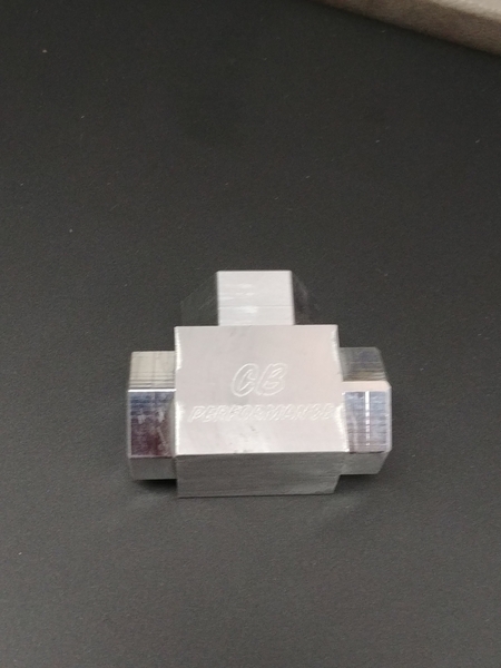
Why am I talking about this, you ask? In that first order is a CB Performance fuel tee. This screws directly to the tank and allows a feed and return line without cutting any holes in your tank. This twenty-something-dollar part is holding up the EFI, as I can't install the tank, yet.

I suppose I'll have to become a contributing member now that I'll be benefitting more from this site. Dan Piperato Performance, or DPP.

Here's some photos of yesterday's efforts. I really like the look of the black nylon-braided fuel hose. It does have a metal mesh under the nylon braid and is specifically designed for gasoline and alcohol fuels.

However, it is not the easiest stuff to work with. As you push the hose into the fitting, you need to take a small screwdriver and tuck the braid in as you push. It takes a lot of effort especially after six of the fittings. My hands and shoulders are a bit sore today LOL!20210223_16264420210223_19073520210223_19045520210223_19061120210223_212536

The last picture is my fuel pump and filter mount, similar to what Carlos diss on his car. The fuel comes in at the top left from the tank into a pre-filter. There is a Tee that splits off to my heater fuel pump. The hose goes into the EFI pump, then out to the already mounted Subaru post-filter.

From the final filter it will travel to the feed line in the tunnel and go to the passenger side fuel rail. Then across to the driver's side, then to the regulator. After the regulator it goes to the return line in the tunnel and back to the tank.

I completely disassembled the regulator and found the diaphragm in good shape. I cleaned the parts up in my ultrasonic cleaner, dried them with compressed air, and reassembled.

The Gates Barricade EFI hose is very tough and difficult to get over the barbs. Even with silicone spray or oil(I tried both) it takes a lot of twisting and pushing.

Attachments

Images (4)
  • 20210223_162644
  • 20210223_190735
  • 20210223_190455
  • 20210223_190611
Last edited by DannyP

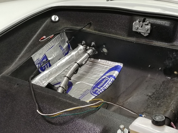
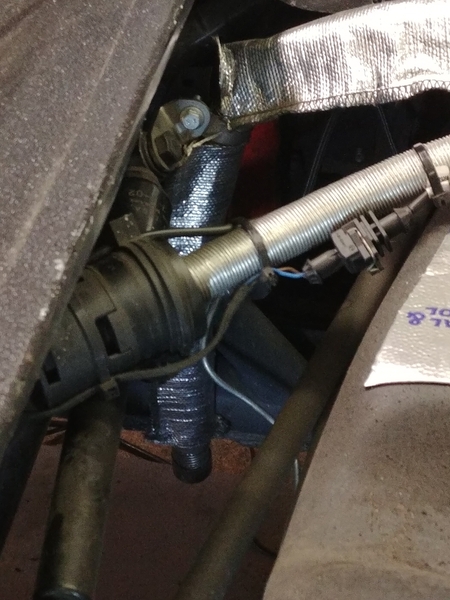
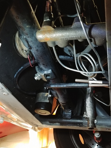
These are for @Gordon Nichols and are of the gas heater install, specifically the combustion intake and exhaust routing. 20210223_194751_HDR20210223_19490220210223_19492220210223_19513520210223_195340

In the first pic you can see the wires for my gas gauge and the trailer harness that I'm reusing for fuel pump power.

The thermal barrier works well on the fiberglass and is also applied to the bottom of the tank. The sleeve over the exhaust works well too.

You can see how little of the heater exhaust is visible in the last picture.

Attachments

Images (5)
  • 20210223_194751_HDR
  • 20210223_194902
  • 20210223_194922
  • 20210223_195135
  • 20210223_195340

@Alan Merklin Third base? LOL! Actually you just gave me a thought. No torch, but I'll try a heat gun on the Gates hose. Maybe it'll ease the installation. Thanks!

Thanks guys, I really love building stuff.

In addition to everything else I'm doing, I am also the moderator of spyderclub.com now, since Larry passed away last fall. There is nowhere near the amount of traffic as there used to be, but somebody has to maintain the site, approve new members and help the guys that are new to Spyders over there.

Ed, I salute you...Snoopy Salute

Having that coffee maker out in the shop just makes sense.

I didn't start out as a coffee/expresso snob, it just happened when I wasn't lookin'.  I was about 40 when I started with my final company.  They were losing money like water from a spring and a bunch of us (The 'Gang of Twelve') were recruited in to "turn the place around".  That took almost three years before we started making any serious money, then we never looked back.  I was in Engineering New Products and one way we realized to increase design productivity was to (over)caffeinate the Engineers, so we brought in some Bunn coffee machines for our three break stations and gave everyone free coffee.  IIRC, back then it was Folgers or Maxwell House for the Americans, and some Turkish blends for the Eastern Europeans (Mostly Israelis).  We all quickly realized that American coffee kind-of sucks so we started giving our Euro sales offices perks (see what I did there, Stan?)  like, "You bring in that big Bank customer who's on the fence and we'll give them a special tour through the (secret) Engineering labs - That'll impress them enough to buy our stuff".  

It worked, and in the mid 1990's our product line really took off and we were growing over 350% per year.  We were bringing in Engineers from all over the World and they all had their own coffee preferences; Brazilian, Colombian, Trinidadian, "Jamaican-Mon" Puerto Rican and, of course, a few from eastern Europe and Africa.  Trust me, ALL of it was better than Folgers/Maxwell House.

About that time, one of our sales ladies sold our product into both the largest bank and three different telephone companies in Italy, with help from a few Engineering tours.  Those deals, alone, guaranteed her lavish retirement.  To thank us, she sent over six Cimbali Cafe-size coffee/expresso machines.  These were the ones you see in high-end cafes.  Very pretty, lots of brass, copper and chrome but the real bonus was that they made, with the use of all those different beans being shipped in, fabulous coffee.  We were all drinking Turkish first thing in the morning, Yaucano from Puerto Rico at mid-morning (that stuff blows your socks right off as an expresso), Ethiopian with lunch, Brazilian mid-afternoon, Colombian with dinner (we worked pretty late) and then we all sat up all night thinking about work because we were so caffeinated that none of us could sleep.  IIRC, I was getting about 3 or 4 hours sleep per night back then from drinking 2 - 3 POTS of expressos per day.  I'm amazed I never had a heart attack.

I would get in around 06:30 and usually was the only one there except for Hannah Moreshet.  Hannah taught me how to really make expressos with those machines and was also a fabulous microcoder (person who writes the internal software of a computer) who wrote a lot of the error correction code in our flagship line of large-scale disk storage.  Suffice it to say that if you pull out a credit card anywhere in the free world, chances are that the data in your account is secure, somewhere in the information chain, because of her code.

So whomever got in first would make a couple of large mugs (we got used to quad-expressos after a while) and we'd share our cup and talk about Engineering stuff until more people arrived.  By that time we would be on our second quad-expresso and just carry on for the day, the expresso cup always at least half full and the machine a short walk away, where you might meet other engineers you could talk with about what's going on - MBWA, "Management by Wandering Around".

That was life at EMC in the 1990's.  We grew from losing money to having a $14 Billion sales year in 8 short years, over-caffeinated all the way, but wow....  

What a trip it was!

That is quite a story Gordon, it reminded me of going to Paris in early 80's and waking up to probably the best coffee I had ever had at the time.   After that time it seemed that North America ventured into better coffee as time went on.  Today there is St- Arbuck at each corner. It feels like going to Québec, where there is a town dedicated to each Saint at every corner.

One of our past Speedstah-Guys, Mike Cochrane (remember his car, "Fern"?) is SVP and "Chief Caffeinator" at a prestigious coffee and machine supplier out of Quebec City, covering all of North America.  We're friends on FB but I don't know how active he remains, Speedster-wise.

A terrific cup of coffee is a wonderful, almost spiritual thing.  (But not from Folgers or Maxwell House).  I now get really nauseous from a single cup, so tea's my game.

Sorry for screwing up your absolutely amazing thread, Danny.  I'll get a photo of my heater exhaust (mine is really simple).  My combustion intake has no intake pipe.  The heater sits up off the deck on mounting legs with a 3/4" gap, heater to floor, and no apparent place to attach an intake manifold so I just left it at that.  Seems OK.

And now back to our regularly scheduled EFI upgrade posts (which are fascinating, BTW).

Baby-Yoda-coffee

Attachments

Images (1)
  • Baby-Yoda-coffee
Last edited by Gordon Nichols

.

@DannyP posted:
.

Au contraire, Mitch.

Ed may be having a bit of fun with us all. But since I know him a fair bit...I can say without hesitation that I'm positive he actually HAS and USES that machine. No doubt...


OK, Danny, if you'll vouch for it, I'll accept that Ed uses such a device. You know him better than most of us.

But he keeps it out in the garage and he doesn't say that he actually drinks what comes out of it.

He was also a little close-lipped about the origins of that barber pole fabric he used in the Spyder. You don't think he used the 'coffee' from that thing to dye the material and leave it with that distinctive patina, do you?

I mean, Ed has been known to home-brew a lot of his solutions (see what I did there, Gordon).

Anyway, congrats on your new enterprise, Danny. It's rare that any of us has an opportunity to benefit mankind like you're doing.

And sorry for the extended coffee break.

.

Back to EFI. My last picture of the fuel pump board didn't post.20210223_212536

To check the calibration of the coolant(cylinder head) I used a pot of water on the stove. To check my intake air sensor I used a heat gun. It responds really quickly, so I think my homemade sensor works just fine. I measured a bunch of temps to make my own calibration if needed.

20210224_12032020210224_165743

I put a clamp on the fuel rail to support the AN hoses on both sides.

20210224_161030

It's kind of hard to see, but both filters and pump are installed and connected. The front beam area is pretty busy, not any real room left. Power is hooked up and the relay works. I've got to connect the tank hoses and the fuel portion is done.

Maybe tomorrow I'll wire the injectors and remaining sensors.

Attachments

Images (4)
  • 20210223_212536
  • 20210224_120320
  • 20210224_165743
  • 20210224_161030
Last edited by DannyP
@edsnova posted:

Looking real good, Danny. And good luck on the engine/trans biz. The VW world needs another good engine and transaxle guy.

Thanks Ed, that means a lot.

I've got to build a test stand. I've got time, the heads and manifolds are 6 weeks out from CB. I'll use my existing engine stand and a chunk of bellhousing with just the starter section. I happen to have two extra starters and I know a VW guy with lots of junk transmissions laying around. I need a lawnmower tank, electric pump and a battery. How hard can it be?

Last edited by DannyP

I'm continuing to make progress.

Today I built the injector, TPS, and temp sensor harnesses. They are run to the ECU, but I have to secure them to the frame then terminate them.

20210225_14072820210225_140705

This is how I did the harnesses. I taped then pulled wires into 4 foot heatshrink. Mig wire works as a fish, you have to bend a hook in it and pierce some insulation before you tape it.

My bench is pretty messy, but hey it's a working shop.

20210225_103738

To be continued, tomorrow.

Attachments

Images (3)
  • 20210225_140728
  • 20210225_140705
  • 20210225_103738
Last edited by DannyP

All the wiring is finally done. Well, except for 4 wires to the stepper idle control that I'll be adding later after it's running...

20210226_10455520210226_105029

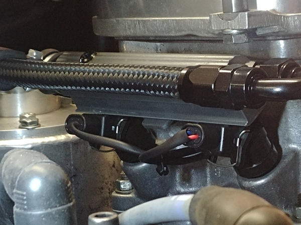
This is the driver's side. Two injectors and TPS. You can also see the vacuum takeoffs in there. The two cylinders T together, then goes to another T at the fuel pressure regulator. The other side joins this side in the middle of the firewall, finally ending at the ECU(you can see the hose in the final picture).

20210226_10495920210226_110147

20210226_110203

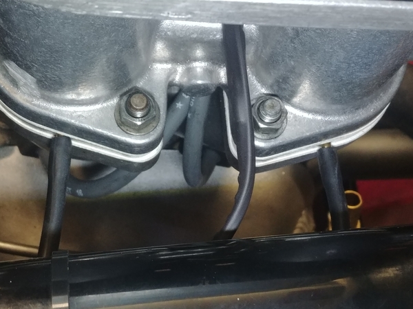
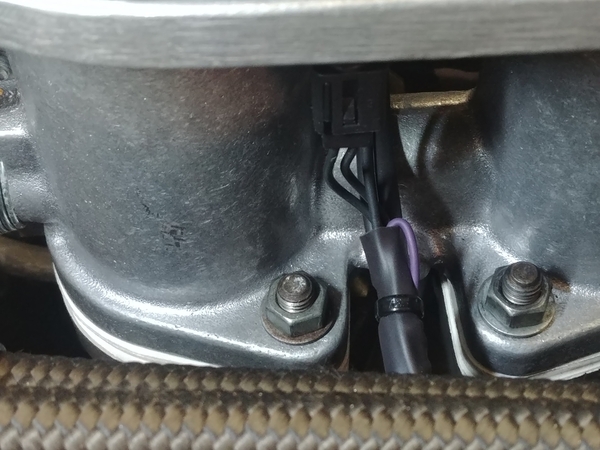
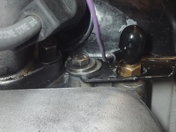
The passenger side has the other two injectors, and temp sensors for the cylinder head and intake air. The violet wire follows the intake manifold down to the factory temp sensor location. I ran a 1/8" pipe thread tap in there as that is the sensor's threads. You can barely see the intake sensor.20210226_183201

All finished. No fuses were blown or smoke was released. @dlearl476 see the T & B tool?

After this I turned on the laptop and connected. Temp sensors calibrated. Throttle position calibrated. AFR verified same reading on Tunerstudio and on the little display.

If I ever get my fuel T from CB and install the tank I'm 100% ready for the first start! Yay!

Attachments

Images (6)
  • 20210226_104555
  • 20210226_105029
  • 20210226_104959
  • 20210226_110147
  • 20210226_110203
  • 20210226_183201
Last edited by DannyP

I finally got my CB Performance fuel Tee!

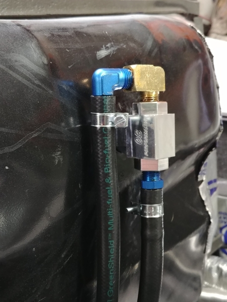
I installed the Tee, threaded/barb adapters, EFI hose and clamps to the tank. Dropped the tank in and hooked to the pre-filter and return line.

Turned the key on and got pressure. No leaks at the front. No leaks at the fuel rails, injectors, or braided hoses.

I had a small drip on the feed side though. It was where the hard line adapts to AN-6 at the engine firewall, right after the center tunnel. I took it apart, cleaned and dried, then reassembled with some fresh Permatex.

All good now! I need to get a couple gallons of fresh Ultra 93 and can try to start it up tomorrow. My friend Lenny is coming tomorrow and I'll appreciate the help.20210305_14422920210305_16273420210305_181410

I'll be sure to take some video and put it on YouTube.

Attachments

Images (3)
  • 20210305_144229
  • 20210305_162734
  • 20210305_181410
Last edited by DannyP

Super-Sano look there, Dr. P.

Hot Rod Jimmy, in my town, was helping his son do an engine rebuild on his Porsche 996 and they were both working on it over a few months.  When it came time to fire it up, Jimmy’s son wasn’t there.  Jim hits the key, it springs to life, he gets out and looks in the engine bay and it is engulfed in 🔥

He kills it, gets a fire extinguisher and puts it out with very little damage, then discovers that one of them didn’t tighten the connection at a “T” and at EFI fuel pressure it was really pumping fuel out.  There was probably enough blame for both, but they just took it in stride and the car was saved, anyway but the morale of the story is; Be like Dr. P, not like Hot Rod Jimmy.  Energize just the pump and check for leaks before you start it up!

🔥 happens.

Most of the time it’s contained.

You and Lenny gonna crack a bottle of champagne (or other sudsy adult beverage) over the nose when it cranks up?  Come to think of it it might be better to skip the "crack it over the nose" part and just enjoy the contents.  Tell Lenny I said "Hi!"

I'm saving a bottle of something to crack on a blue nose out in the midwest. After I flog the crap out of it! It's only a day's drive away...

IT RUNS!!!

It took a little to get it to fire, the injectors weren't firing at first. I think it took a little time to bleed the air out. There was fuel in the rails and to the injectors, but how do you bleed it out other than to fire the injectors, right? Then the pulsewidth for the injectors was WAY too low, not nearly enough fuel. Once we got that sorted it fired right up and ran at 800 rpm. Changed the air and fuel(more of both) and it settled into a 900-1000rpm idle.

I'll take video when I can get a chance. Lenny and I were very busy programming and tweaking just to get it to smoothly idle and accelerate. It wouldn't accelerate at all, the AE(acceleration enrichment) had to be adjusted. Boy does it jump off idle with absolutely NO bog though! Bye bye carburetors...

It's going to be in the mid 60s in the middle of next week. YEAH!

It's learning a brand new language for me. It's gonna take some time.

I did some reading and video watching last night on tuning and maps and such.

First off, at the very beginning when you punch in the engine constants, you need to get that right. After you type them in, THEN you do a fuel calculation to get a basic VE table(volumetric efficiency or required fuel).

With ITBs(individual throttle bodies) the setup is different from most cars. Port  injection sprays the fuel into the intake port on the back side of the valve, and is pretty efficient(but not quite as good as direct injection). If you check the box for throttle body, the program assumes it is a SINGLE throttle body, just like the original GM throttle body injection. Simply replace the carb with one throttle body.

https://help.summitracing.com/...ection-style-mean%3F

We don't have the injectors firing on the backside of the valve and we don't have one big spray for a V8. We have individual throttle bodies and injectors and individual intake tracts, somewhere in between the two choices in Speeduino. The difference in the fueling is almost 10% more for throttle bodies, and is about what I added to my original map to make it idle smoothly.

I've started back from scratch with this revelation.

Critical things: Crank trigger angle, falling edge/rising edge trigger, going high or going low to fire coil(and not release smoke!), fuel table.

Another biggie: TURN THE AFR compensation OFF! You need to know what the AFR is, but you want to manually control it. This is super important, you don't need the ECU trying to undo or modify the change you are trying to implement, you'll end up chasing your tail.

The other thing I noticed was how fast the head temp increases when the mixture is too lean. I richened it up and the temp came down IMMEDIATELY. I think our engines are fuel-cooled as much as air-cooled LOL!

There is a youtube guy who makes videos. All his car builds are Speeduino-based(and left hand drive). I think he lives in a British Empire island nation somewhere but haven't looked it up yet. His name is Dwayne and his channel is DC Werks. Very knowledgeable and down to earth, only a touch difficult to understand with his slight islander accent. I'm really learning a bunch from him, he has great tutorials.

https://www.youtube.com/watch?v=pwCq9t_DLr0

More to come later.

Last edited by DannyP

"The other thing I noticed was how fast the head temp increases when the mixture is too lean. I richened it up and the temp came down IMMEDIATELY. I think our engines are fuel-cooled as much as aircooled"

Sounds just like an airplane!

With Subies if you modify the air intake, and you do not check your engine ECU program,  you could lean out the mixture so much as to heat up the combustion chamber and blow the engine.   Something that I learned from my subie tech who builds race cars.

@DannyP I think that you should go visit “Dwayne” for an in-person training session of, oh, say....  A week or two.  It will be infinitely better than Youtube videos, simply because in your off hours you could be sitting on a beach in 80° weather drinking Rum Swizzles!  The Rum is really good down there, too.  We stopped there and at Martinique on a cruise years back.  Both islands are gorgeous.  You might even decide to stay!

Yeah, ship the car to St. Lucia. You'll give me the money for shipping both ways, right, Gordon?

As I mentioned on Joe Fortino's post, it was 57 today. Garage and side door open wide!

I installed some nutserts in the front trunk so I could bolt the tank in MUCH easier. It used to be a "fun" time with the wife getting those four bolts in. Got the tank install checked off the list, and re-installed the aluminum under-pan in the front.

Then moved on to more tuning. I got the start/warmup a little better and have the warm idle nailed, AFR sits at 14.1 to 14.3, cylinder head sensor is at 180F. Where the sensor is located gives about 50F LESS than the center by the plug, so idling my heads are at 230F and STAY there, no temperature creep at all.

I started playing with injector voltage correction, the fuel sprayed varies quite a bit with battery voltage. Each injector has a curve, but I didn't get a spec. sheet from CB. So you have to wing it. Mostly my voltage stays at 13.5 to 13.8, but this curve is for when your regulator dies, or your gas heater AND lights are on, which drops the voltage down to 12 or 12.5.

I started playing with the VE(volumetric efficiency or fuel load) table, changing cells and revving the motor slowly(no acceleration enrichment is programmed yet). Anyway, getting there, slowly.

I worked on the injection more today. I took a 10 mile drive after it was warmed up. I turned on Autotune and initially set it to easy(cell change resistance). Once I get it closer I'll change the setting to normal.

It seems to have MORE power than with carbs, especially down low around 2000 rpm and up. And it's smoother. I'm using MAP(manifold air pressure, or vacuum since I have no boost) for load sensing right now. At idle I have 48 kpa(kilopascals) which is about 14 and change inches of Mercury. Not what a stock motor has, since my cam is lumpy and lots of overlap, but more than enough to use for load sensing.

The cylinder head has stayed the same temp as the other day, right around 180. After I came home and shut the motor off, the intake air temp went up to over 200 F, which is an example of heat soak. It cooled right off when I restarted it. Cooling fan came on a couple times, the engine seems to warm up quicker when the AFR isn't bloody rich!

It was 55 today and sunny, no wind. It was a beautiful day to be out and about with EFI!

Iron Maiden. The shop had some Wo-Tang type designed stuff done, so I had to go the other way and had some T-shirts made with the shop name done in the Maiden letter style. They're just for the employees.

Syc maiden 2

Danny, PM me your sketch and I'll see if I can clean it up and turn it into a computer graphic so you can send it off for cards, T-shirts, magazine ads, and bill boards.

Attachments

Images (1)
  • Syc maiden 2

I haven't updated this in a while.

I've had several nice 60-65 degree days(Sunday through today) after we had a short cold spell. I've been tweaking and tuning and today I did some WOT(wide open throttle) testing. I've got it right around 12 to 12.5:1 and BOY DOES IT RUN! 90 comes up QUICK! Must be the absolutely no restriction of the 48mm throttle plates. And there is no pinging at all, even running a bit leaner than with carbs. I copied my spark curve from Megajolt(converted the 10 x 10 table to 16 x 16).

I've still got some warm up work and stepper idle speed adjustments to do. And I've started playing with acceleration enrichment today. Still the AFR control is turned OFF, I've got to get it close first before that control gets engaged.

I'm strongly considering a couple local dyno places, one in particular as they have experience with Megasquirt and it's control program Tunerstudio. It isn't hilly enough close by my house to really load the engine going up hills for long periods. I live right near a river, curvy roads but flat. I could go to some hills, but I need to drive a half-hour to do it and then there would still be traffic and pedestrians to worry about.

I'm thinking a safer and quicker solution is a chassis dyno.

It's been bright and sunny out, but there are no leaves at all, not even buds yet. Makes finding some shade so I can tweak the tune and see the laptop a bit difficult...

Last edited by DannyP
Post Content
×
×
×
×
Link copied to your clipboard.
×
×