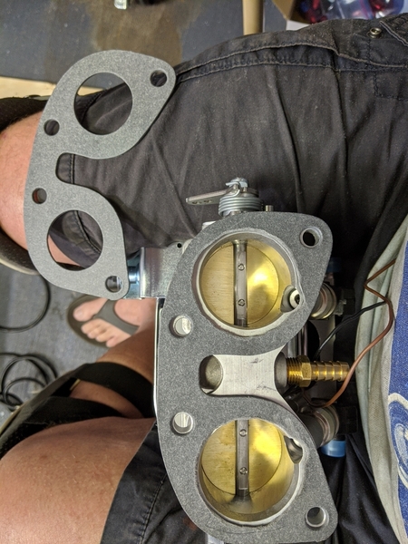
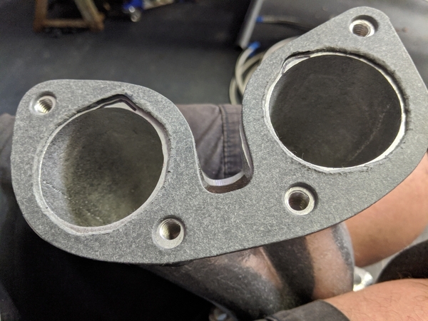
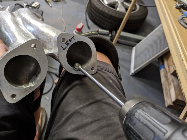
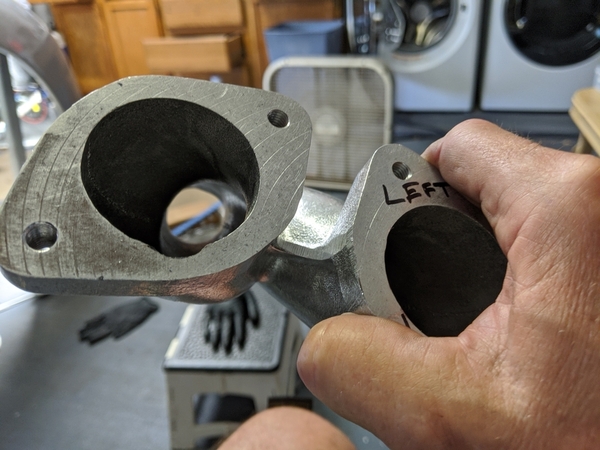
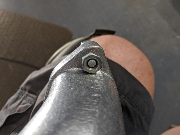
Today's update: built out the fuel pump system from the gas tank to the engine bay; built both of the throttle body/manifold assemblies; tweaked the throttle bodies to work with the CB Performance manifolds; ported and gasket matched the manifolds to give clearance for the injector spray.

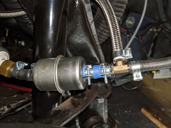
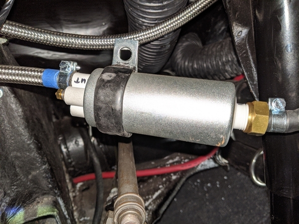
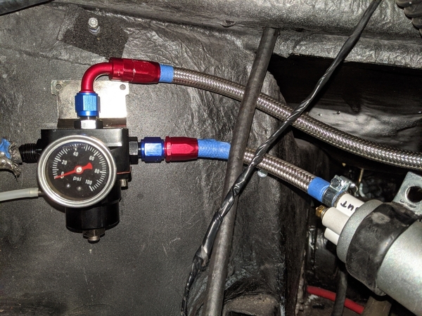
Here's the gas tank side. The tank feeds a brass T connected to the first gas filter and the fuel return fitting on the regulator. The first filter connects to a Powerco high pressure inline fuel pump (around $50 from Amazon). The pump feeds the pressure regulator which feeds the second gas filter. The second filter connects to an AN6 steel covered fuel line that runs to a firewall AN6 bulkhead T that provides 2 AN6 fittings in the engine bay.

Tank side

IMG_20200713_054406

Short run to brass T then filter and pumpIMG_20200713_054351

Brass T with fuel return from regulator

IMG_20200713_054453

High pressure pump

IMG_20200713_054439

Regulator

IMG_20200713_054507

2nd filter and feed to the engine bay and vacuum line from manifolds to the pressure regulatorIMG_20200713_054514

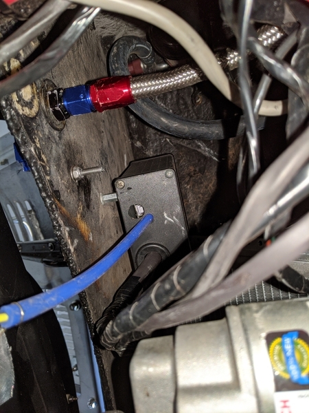
Gap between firewall and backseat. 6AN bulkhead fuel fitting and Speeduino mounted on back of the firewall. Blue hose is manifold vacuum

IMG_20200713_095909

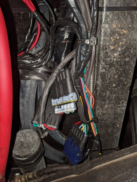
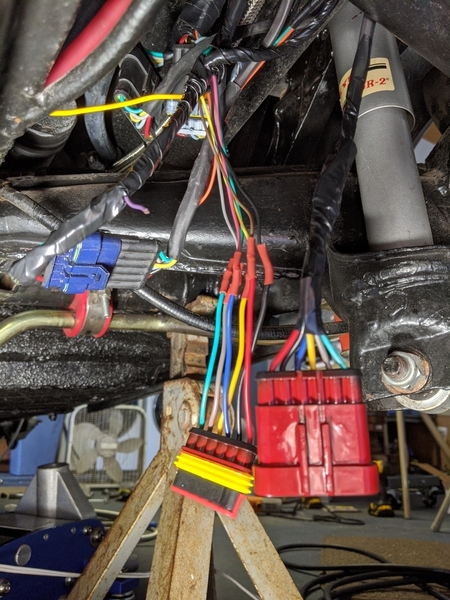
Speeduino connections broken out into 6 pin waterproof connectors

IMG_20200713_100139

Splash guard installed underneath Speeduino

IMG_20200713_100310

GM intake air temperature sensor tied to the stake inside passenger side air filter. Wires run through 3/16" hole filled with black RTV.

IMG_20200713_111717

Gasket matched to throttle body

IMG_20200713_121000

Gasket used as template for porting manifold for injector

IMG_20200713_122428

IMG_20200713_122843IMG_20200713_122856

Tomorrow I'll build out the fuel hoses in the engine bay and finish wiring up the injectors, throttle position sensor and intake air temperature sensor.

Attachments

Images (14)
  • IMG_20200713_054406
  • IMG_20200713_054351
  • IMG_20200713_054439
  • IMG_20200713_054453
  • IMG_20200713_054507
  • IMG_20200713_054514
  • IMG_20200713_095909
  • IMG_20200713_100139
  • IMG_20200713_100310
  • IMG_20200713_111717
  • IMG_20200713_121000
  • IMG_20200713_122428
  • IMG_20200713_122843
  • IMG_20200713_122856
@Stan Galat posted:

I have a set each of 40s, 45s, and 48s DLRA Dellortos, as well as a set of 48 tri-jets. I have 4-8 of every idle jet CB makes for Dellortos, and 4 of quite nearly every main, and 6 sets of 4 air correction jets. I'm not very moderate when I get into something.

I'm ready to try EFI, I think.

Shoot, Stan, next time I need something, I'll get in touch with you. The local place I used to source parts just moved to Blackfoot, ID.  Which is actually one day further away from DellortoShopUK now.


Dang, I just realized I should have snagged a variety of ORings when last I saw him. I had to buy a new set of throttle plate screws when I changed my venturis.

es 

Last edited by dlearl476
@dlearl476 posted:

Dang, I just realized I should have snagged a variety of ORings when last I saw him. I had to buy a new set of throttle plate screws when I changed my venturis.

Doesn't the venturi come out the top when you change it? All you need to remove is the carb top IIRC. I did rebuild a set of Dellortos once. I don't remember removing the throttle plate or the throttle shaft.

I do remember Webers have a single set screw for each venturi.

Mike: keep the pics coming, you're teaching me how it's done!

I was thinking of installing a swirl pot though for pressure feed and return from regulator, back in the engine area. Basically use the existing fuel feed and low pressure pump to feed the swirl pot. If not that, then put a return into the top of the fuel tank(probably smarter and simpler). I've always seen the pressure regulator right at the fuel rail, shorter vacuum line that way.

I try to put together a cost list of what I've got in this project. I think Danny's in the right ballpark.

The cost will vary over time, and is dependent on who's hardware, etc. you are using.

For the complete neophytes (like me), it'd be nice to know "what", rather than "how much". What are the capabilities and limitations of Speeduino?

I'm a mechanical guy, and I think in mechanical terms, so the physical components are the first step to understanding for me. I can "see" what is happening inside an engine (with my mind), software logic is a lot harder for me. Once everything is mounted and loomed, and tidy, I'm aware that the fun's just starting - but there are tuners out there who make a living doing just this sort of thing. I may be comfortable tweaking a fuel map someday, but that days is not today. It took me forever to be able to see what was happening with jets (idle, emulsion tubes, air, and main). This stuff could end up occupying me until I'm no longer ambulatory (which is kind've the point of a hobby).

A basic system would be batch-fire and wasted spark, I assume. It'll need a trigger wheel, a crank position sensor and bracket, throttle bodies, a throttle position sensor, fuel rails, injectors, a higher pressure fuel pump, a regulator (which I need more information on), some means of return to the tank for the fuel. Ignition needs a coil pack. People get really, really detailed about stuff like Delphi wiring connectors, so there must be more to that than I think. If I'm not mistaken, that's the basics. If there's more to any of this, I'd like to know. I know there are huge gaps in my understanding of it.

Air temp sensors? Engine temp sensors? O2 sensor? Other things I'm not thinking about? This (like everything else) must have a sweet spot where you have more than "basic", but not so much that it becomes a mass of wire.

Any tips, hints, etc. are welcome - as is as much specificity as possible. You're a brilliant guy @Michael Pickett, and I'd like to sit at your feet.

@DannyP posted:

!I was thinking of installing a swirl pot though for pressure feed and return from regulator, back in the engine area. Basically use the existing fuel feed and low pressure pump to feed the swirl pot. If not that, then put a return into the top of the fuel tank(probably smarter and simpler). I've always seen the pressure regulator right at the fuel rail, shorter vacuum line that way.

When I tested the fuel system with short hoses out in the driveway, with a fire extinguisher at hand, I was shooting for a returnless setup so I only had to have one fuel line going front to back. That didn't work with my regulator and I'd read about people getting bubbles in their gas tank from the return line dumping from the top. I found the CBP installation manual online and saw that they just used a brass T right below the tank for the return. I gave it a try and it worked. That's why my regulator is up front. I figured I'd rather run a vacuum line front to back than a second fuel line.


@Stan Galat posted:
 

...A basic system would be batch-fire and wasted spark, ... a trigger wheel, a crank position sensor and bracket, throttle bodies, a throttle position sensor, fuel rails, injectors, a higher pressure fuel pump, a regulator ... some means of return to the tank for the fuel. ...a coil pack....

...Air temp sensors? Engine temp sensors? O2 sensor?...

...If I'm not mistaken, that's the basics...


You know, fellas, idle jets are starting to sound like not so bad a thing, after all.


@Stan Galat posted:
 

...This stuff could end up occupying me until I'm no longer ambulatory...


I think Mike went down this rabbit hole because he was no longer ambulatory up around 10,000 feet.

Around here, most roads you want to drive on are under about 6000 feet (and I'm guessing that's true in Peoria, too). There are a few passes at 7000 or 8000, but you're quickly over them and then down the other side (and past the summit, you can coast down, anyway).

My car gets a little pokey at 5000 feet. But then, so do I.

If I'm hanging around up there for more than a day or so, I might tweak the mixture-which-aren't-mixture screws a bit to balance things out again. That's about two minutes gone out of the day.

All things considered, I think I'll be taking a pass on this crank trigger throttle body fuel rail high-speed pump regulator and mapping thing.

Even though it sounds like it would be no trouble at all to get dialed in.


Stan, you've got it right. Intake air temp, engine temp(coolant or oil) or even just a factory type3 style warmup sensor in the head. O2 controller and wideband Bosch sensor. Batch fire and wasted spark is WAY easier on a type1 and is VERY workable.
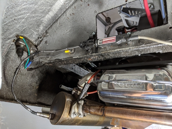
All modern EFI systems adjust the fuel pressure with a regulator. It is usually hooked to manifold vacuum. High vacuum(low throttle) lowers the fuel pressure, Low vacuum(wider throttle) increases fuel pressure. The regulator keeps a specific fuel pressure at all times based on vacuum. This will most probably work well for Mike's engine as it doesn't deviate too far from stock with regards to vacuum pulses.

Stan and I are going to have a more difficult time with LARGE valve openings and big valves. At the very least we'll need to tap all 4 intake manifolds and tap them into a large vacuum accumulator. Lenny had the same pulsing vacuum problem on his Raby type4. The solution MAY be to set the regulator pressure and not use a vacuum input, or only give it a narrow range of adjustment.

Proper injector selection is important here to ensure a wide enough pulsewidth range for all running conditions(lean and rich, hot and cold, and load).

Mike, I also thought of using the existing line as a return, and running a new line to feed the fuel rail from the pump. That's easier in a Spyder than a tunnel/pan car.

@DannyP posted:

Stan, and anyone else that wants to "dive off this cliff" with EFI:

http://performancefuelsystems....rface-TechCorner.htm

LOTS of good learning out there to be had.

Thanks for that, Danny. As soon as I started reading, the light went on over my head. I've always been confused why injector pressure needed to vary at all, and wondered even more why vacuum was used to do it. Vacuum seems so... uncivilized for EFI.

As the article says (in so many words), the idea is to maintain a constant pressure in the fuel rail relative to what is occurring in the manifold. If the manifold is under a lot of vacuum, the regulator needs to supply less pressure to keep a constant relative fuel rail pressure. Atmospheric pressure is 14.7 psi absolute (absolute being a perfect 30" vacuum), therefore 2" vacuum roughly equals -1 psi (atmospheric). If the manifold vacuum is 10", then the regulator needs to back off the pressure about 5 psi in order to supply the same relative pressure to the fuel rail.

Brilliant and elegant. I learned something new today. Thanks, @DannyP.

BING!!! A carb uses changing pressures.  The injection needs a consistent pressure in the fuel rail relative to the manifold because it meters fuel flow using time (how long the injector is opened) and that's easier to do accurately when that pressure differential is constant.  

Once I got that the mapping is telling the injectors how much time to stay open (richer is longer, duh) they started to make real sense when looking at them.  It's fascinating to look at fuel maps, ignition curves and dyno charts together. Then change a value (the shape of the fuel map or Ignition curve) and see the change in the dyno chart, the change in the shape of that curve relative to the others. The first time it clicked was a real Matrix moment....like....I can see the universe man!

I got the pulse timing straight off, but the floating pressure seemed antithetical to the idea of controlling the fuel. All of the sudden, there is was - it's critical to controlling the fuel.

I'm always amazed at how smart people can be when they focus their Jedi minds on a problem, because the vast bulk of humanity generally seems to be driven along by impulse and fear.

Last edited by Stan Galat

The fuel pressure regulator on an EFI is very elegant and simple. It helps to remember that the length of the fuel pulse (i.e. time) is what's being varied by the fuel map, not the size of the nozzle as in a carb with idle and main jets and all.

And 30-45 lbs of static pressure does wonders for your atomization.

As for "capabilities," the arduino/Speeduino system seems to have a lot out of the box, manifold pressure sensitivity way more than needed in a typical NA application, and even fine for boost up to 20 lbs. Just a much broader array of potential situations than a well-tuned Weber can manage. Hence the usefulness in mountain areas.

Hence the ease of start-up.

Hence the better fuel economy.

Hence the better/smoother throttle response.

The Achilles Heel is the idle air control valve for warmup. A mechanically controlled vacuum leak machine that can and will fail. Eliminating this is much of the reason drive-by-wire (as opposed to throttle cable) is the way modern cars go. 

But you can get by without it. And VW hotrodders are all about rough cold-starts...

Given that a pair of new Weber 44s, a fuel pump and filters can easily top $1,000, an Speeduino EFI rig with ITBs at a sub-$1500 price is hard to argue against.

Stan, no problem at all.

Ed, I see you may be coming around......

Speeduino offers the option of using a stepper motor(modern way, just before drive-by-wire throttle) for IAC(idle air control). That's the way I'd go. Truly, you could just use one big throttle body, but what fun would that be?

Four good-sized hose bibs plumbed to an intake air control valve with a mini air filter on the other side. Controlled air leak indeed.

Or, like you say, don't worry about it, let it run a little rough for a few minutes.

I'm glad there's enthusiasm for an "inexpensive" approach to fuel injection and ignition. If I get it working, I'll be glad to share the problems, solutions and limitations encountered along the way. I also very much respect the "if it ain't broke" approach.

The Tunerstudio software that works with Speeduino and the Megasquirt siblings has an autotune feature. You set up a spreadsheet (RPM x Manifold Air Pressure) and fill in the target air fuel ratios you want. Then you just drive around and the software adjusts your fueling to try to achieve the A/F targets. It worked well the last time I did serious tuning (2010).

If I remember correctly, you still need to fiddle with the acceleration enrichment map to get rid of the lag and as Ed noted, the idle air table (think of it as an electronic choke). When I lived in Rhode Island, idle air was a big deal because of the wide temperature ranges. Here, I've brought the wiring out in case I need to add it, but don't think I will.

I've run into some problems with my CBP Panchito manifolds that slowed me down today. They don't fit like the cheap eBay Chinese set I used for mock up, so a lot of grinding is getting done. It proudly says USA on the side, but you'd think they'd clearance the sides so a 13mm nut could actually make a full revolution. Heck, that's behind "one flat at a time" territory.

Ok, enough complaining, I'm still having fun.

IMG_20200714_115705

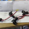
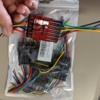
I spent the morning building out the wiring harnesses for the fuel injectors, intake air temperature sensor and throttle position sensor. I've got the version of Speeduino that has a 40 pin IDC connector on the board. I bought a connector with pigtails to get it out of the case and then I broke up the connections I needed into a number of color coded 6 pin - CHEAP - waterproof connectors. That way I can easily remove the Speedy if I needed to do a swap (I've got a spare) and you can easily break out the connections for troubleshooting using another pair of connectors wired back-to-back ( more than most of you want to know - if you want details PM me). That's how I came up with the location of the spark coils vs the location of the Speedy. It turned out that the coil jammed the missing tooth crank sensing circuitry INSIDE the case, not through the cabling. I put the coil on one side of the shroud and the Speedy on the other side. Fiberglass doesn't shield interference worth a flip :-) 

Spray paint color coded

IMG_20200714_091016

Bag of 5 connectors - Amazon ZYTC 6 pin $12.20MVIMG_20200714_064445

Spartan 2 Wideband O2 controller w/sensor $125 from WTMTronics

IMG_20200714_103738

Attachments

Images (6)
  • IMG_20200714_115705
  • IMG_20200714_105253
  • IMG_20200714_091016
  • IMG_20200714_103738
  • MVIMG_20200714_064445
  • IMG_20200714_054325
Post Content
×
×
×
×
Link copied to your clipboard.
×
×