Mike has described this perfectly.

The last time I had a horn issue (like yesterday) it worked fine when I needed it, but if I made a tight left U-turn with the steering against the left stop it would beep until I turned back right.

Turned out to be the wire jumpering ground from the steering box to that wire up the center of the steering shaft.  The electrical lug providing the jumper was slightly to one side and touched the steering shaft flange when turned all the way to the left (and forced) because the rubber coupler distorted slightly from the torque, allowing them to touch.  A slight adjustment on that bolt to swing the lug out of the way and all's happy in the world again.

Still, it's always sumthin with these little cars.

I’m running with my horns wired directly, no relay.  So I’m good to go.

But my curiosity is nudging me to follow up on this a bit, so I may.  What follows is nothing more than discussion and documentation.  

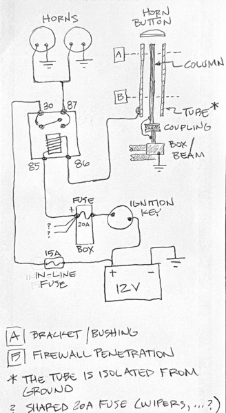
What Gordon, Mike and everyone else has said has improved my understanding of VW horn wiring.  Here is sketch with a bit more detail showing what the circuit should look like using a relay to power two horns in my car.  I think.
DB04B0B5-ADC3-4B1B-86FF-5E9B5646B702

When the key is turned on, juice is just looking for a path between terminal 86 to ground.  Ideally this path to ground is only provided by an intentional horn button depress, which electrically shorts the steering column tube to the column itself which is grounded.  The resultant current flow through the relay coil creates sufficient magnetic field to close the relay switch, which allows current flow through the horns, hopefully loud enough to alert the driver of the large truck backing up towards me.

Clearly for this to work, the column must be electrically insulated from ground, and the tube and column need to be isolated from each other. Failure of either of these requirements can lead to unintentional horn actuation.

So back to my experience, which was: 1) turned key on, horns stayed silent, 2) pressed horn button, horns sounded off, 3) released horn button, horns remained on!

I performed a simple bench test of the relay, it worked as expected (but with less current flow than when connected to my horns).

I made some resistance measurements, but I am now treating them with suspicion until I can obtain some known resistors to verify my old ass cheap meter is working properly.  If not I’ll buy a new one.

So until I can make some reliable measurements, the theory I have is that I do have some leakage to ground at the tube.  If it was a dead short to ground the horn would sound as soon as the ignition key was turned, so I don’t have a dead short.  The leakage does allow some current flow through the coil but the magnetic force created by this low current is not enough to close the switch.  When I press the horn button, current flow through the coil rises, magnetic field increases and the switch closes.  When I release the horn, current flow drops back to the low level allowed by the tube leakage to ground.  The weak magnetic field created with this low current flow just happens to be enough to prevent the switch from opening.

I’m giving myself a 1 in 4 chance that my theory is correct.

I’ll share anything I learn from additional experimentation if the mood strikes me to experiment.

In the meantime, I need to start another thread about my recurring shifter woes.  Always sumthin.

Cheers,

Jon

Attachments

Images (1)
  • DB04B0B5-ADC3-4B1B-86FF-5E9B5646B702

.

Jon, I think you're discovering one of the joys of working on these cars.

We enter a curious world where traditional laws of physics and electricity don't necessarily apply. Messieurs Ohm and Kirchoff would be uncomfortable here. It's a sort of middle ground between science and superstition.

Currents flow where none should exist. Air bubbles appear out of nowhere in fuel and brake lines. A car going down a straight road suddenly veers off course as if an unseen hand is on the wheel.

I'm pretty sure Rod Serling drove a Speedster.

.

Last edited by Sacto Mitch

This needs to be stated to every perspective speedster owner !

We enter a curious world where traditional laws of physics and electricity don't necessarily apply. Messieurs Ohm and Kirchoff would be uncomfortable here. It's a sort of middle ground between science and superstition.

Currents flow where none should exist. Air bubbles appear out of nowhere in fuel and brake lines. A car going down a straight road suddenly veers off course as if an unseen hand is on the wheel.

I'm pretty sure Rod Serling drove a Speedster.

Thankfully I trolled this forum for quite sometime before taking the plunge, so I had a very good idea what replica speedster ownership would likely be.  

There was something else you’ve said once Mitch that I’ve found to be true.  I’ll paraphrase here, but your point was these cars allow you to see how things work, which allows you to see what is wrong.  The small amount of work I’ve been able to perform on my car to this point is because that notion is true.  And of course because of the generous support of the great people of this forum.  And Google.

And by the way, I’m cool that my red plastic Hella horns peek through the horn grills.

@Jon T posted:

Thankfully I trolled this forum for quite sometime before taking the plunge, so I had a very good idea what replica speedster ownership would likely be.  

There was something else you’ve said once Mitch that I’ve found to be true.  I’ll paraphrase here, but your point was these cars allow you to see how things work, which allows you to see what is wrong.  The small amount of work I’ve been able to perform on my car to this point is because that notion is true.  And of course because of the generous support of the great people of this forum.  And Google.

And by the way, I’m cool that my red plastic Hella horns peek through the horn grills.

I let my red horns shine through the front grills the whole time.

@Jon T posted:


I made some resistance measurements, but I am now treating them with suspicion until I can obtain some known resistors to verify my old ass cheap meter is working properly.  If not I’ll buy a new one.


Hey genius, maybe you should check the batteries in your analog multi-meter.  

OK, to perhaps conclude this thread, with fresh batteries in my meter and the leads to my twin horns disconnected, I remeasured resistance from outer steering tube to ground.  It measured somewhere around 140 to 120 ohm, so clearly the outer tube is not completely insulated from ground.  I tried it a few times making sure my alligator clip was making good contact with the tube.  Then when I pressed the horn button the resistance between outer tube and ground dropped to just a few ohms as expected.  

I’m now thinking my above theory has improved to a 1 in 2 chance of being correct; the relatively low current flow through the relay coil allowed by the 120 ohm resistance between the tube and ground is not enough to pull the relay switch closed, but it is enough to keep it open after the horn button is pressed and released.  I’m a bit surprised that 120 ohms would be enough to cause this affect so of course to confirm I’d need to make more measurements.   To do that I’d need to reinstall the relay or develop a much more sophisticated bench test.  Right now I don’t possess enough curiosity or energy to do either, and I’m liking a 50/50 chance that I figured it out and a relatively peaceful mind.  

The horn works and I think I know why.  I’m considering this a win.

By the way, Michael your reminder about the wire running through the center of the hollow shaft was right on.  I first measured resistance between the outer tube and the shaft and got a dead short.  Huh?  Oh yeah, it’s the wire through the column that counts.  I then felt for a wire jumping across the steering rod coupling and sure enough there was a wire that seemed to come out of the column, ran around the coupling and terminated to the short shaft between the coupling and steering box.  My visibility was limited but that all made sense.  For my ground point I instead used a few locations on and around the front beam making sure I was touching metal.

Have a great weekend everyone!

Jon

Well, that 120-140 ohm resistance from the column to ground makes perfect sense and confirms what some of us have been saying - There is something that is providing a ground path to the steering column that’s not enough to pull the relay arm in, but is enough to hold it once the horn button is pushed.

If you’re curious, you could disconnect the column from the lower dash and then measure the resistance and, disconnected, it should show an open.  There should be rubber or (better) nylon insulators between the column and what it mounts to to keep it insulated.  

As we’ve learned, the horn ground lead connects to the steering column, and the column, the steering shaft inside the column, and the steering wheel bolted to it, are electrically connected to the each other via the column top bearing, so the column, shaft, wheel and horn “-“ side are all one, electrically.  All that stuff is isolated from ground at the steering coupler above the steering box and floating, electrically.  Or supposed to be, not showing 120 ohms.

Then, there is a ground wire that jumpers from chassis ground, through the steering box, across the rubber coupler, through a wire up through the center of the steering shaft to the tab on the  horn button.  The shaft and steering box both have a 2-bolt mounting flange but they are mounted 90° apart at the rubber coupler and are electrically unconnected.  The other side of the horn button is connected to the column/shaft/wheel through a spring on the side of the horn button (sometimes there is another tab on the button to connect a wire from the button to the steering wheel adapter, too).  

So when the horn button is pressed, you simply connect the true ground from the wire running up the shaft to the column/shaft/wheel combo to complete the horn circuit to ground.  

BEEP!

So either your horn button is not completely opening at rest (test it with your ohmmeter for infinity when not pressed) or there is something connecting your column/shaft lightly to ground, 120-140 ohms worth, to find and eliminate.  That can be really tough to find if it is “ghosting” a ground path through something else in the car and that’s why I’ve recommended just living with the horns without a relay.  
Anyway, good luck and good hunting!

All of what I said above changed when I replaced the rubber coupler with a double u-joint as part of my R&P installation.

Previously, the steering shaft was ungrounded because of the flexible rubber disk.  Now without that, the whole shaft takes the place of the wire that previously ran through the center of the shaft.  My horn button side connector makes contact with the shaft through the steering wheel.  I have a '60-'61 shaft. The shaft has a plastic sleeve where it goes through the bearing. With nylon screws, the cancel ring is electrically isolated from the shaft.  The wire from the horn button is connected to the cancel ring and it will connect to the outer tube through the bearing.

When I was making resistance measurements, I found that even the bolts used to hold the rubber coupler together were not grounded on the steering box side (they too measured about 120 ohms or so to ground).  So it was definitely the wire jumper that did the trick, which I presume is common?

My horn button is currently plain.  Just a black button.  The day I decide to replace it with something cooler, once removed I’ll probably spend a bit of time getting more familiar with the bits and pieces behind the button.  (@James007 , do you still offer buttons?)

I have never understood why the wire jumper was used instead of the wire from the shaft didn't just going to the steering box side of the coupler.

I discovered that my rubber coupler was slightly conductive.  That may be what you are experiencing.

I was using two couplers with a spacer between them to move the steering wheel back toward the seat.  I replaced one with a Delrin piece and that eliminated the conductivity issue.

@Jon T posted:

When I was making resistance measurements, I found that even the bolts used to hold the rubber coupler together were not grounded on the steering box side (they too measured about 120 ohms or so to ground).  So it was definitely the wire jumper that did the trick, which I presume is common?

My horn button is currently plain.  Just a black button.  The day I decide to replace it with something cooler, once removed I’ll probably spend a bit of time getting more familiar with the bits and pieces behind the button.  (@James007 , do you still offer buttons?)

I do, I am about to start a new batch of Nardi buttons, but have Moto-Lita style buttons, some Banjo caps and momo style buttons in stock, should have more Nardi in a couple weeks.

Post Content
×
×
×
×
Link copied to your clipboard.
×
×