Thanks Danny. 5/8 master I think and I don't know the slave & never heard the term "pivot ratio." I made the pedal to push the master at exactly the same point as the pedal that the car came with.
Currently bleeding it again.
 Speedster Owners - Automotive Enthusiast Community

Thanks Danny. 5/8 master I think and I don't know the slave & never heard the term "pivot ratio." I made the pedal to push the master at exactly the same point as the pedal that the car came with.
Currently bleeding it again.
Pivot ratio.
Isn’t that the relationship between the movement of the throwout actuator lever to the movement of the clutch pedal?
Like 1/8” at the throwout lever equals 1” at the pedal (like Danny said). Once you figure out the ratio you’ll know two things: 1.) How far the pedal can push the throw out lever for total movement and 2.) where the throw out lever is when the pedal is at rest (adjustable at the throwout lever). The ratio will tell you how close the lever needs to be to touching the throwout to the plate when the pedal is at rest in order to get the plate to release the clutch disk with a “normal” clutch pedal stroke.
I used to adjust hydraulic clutches in buses the same way: Adjust the slave first, so that you’ve got about 1/8” of free play at the throw-out lever, then adjust the pedal end to give you 3/8”-1/2” free play, max, then bleed the circuit. That should get you in the ballpark and final adjustment just brings the pedal and/or slave ends slightly closer in gap at neutral.
Yeah whatever, G. This rig was made and marketed to do what I'm asking it to do on the VW parts I've installed it on. I should not have to calculate any angles or engineer any ratios. The slave ain't pulling enough and it keeps blowing bubbles. The pedal takes a while to come up after I close the bleeder so I'm a little stumped right now. No leaks anywhere I can see (yet). I bled this thing out like a year ago and thought I had a decent stroke on it then. Obviously I do not know my business.
Meanwhile: right front caliper is also leaking. dang.
I messed with the pedals and the hydraulics for a couple hours today and in between doing that (whilst pondering my life choices) I did a little upholstery work.
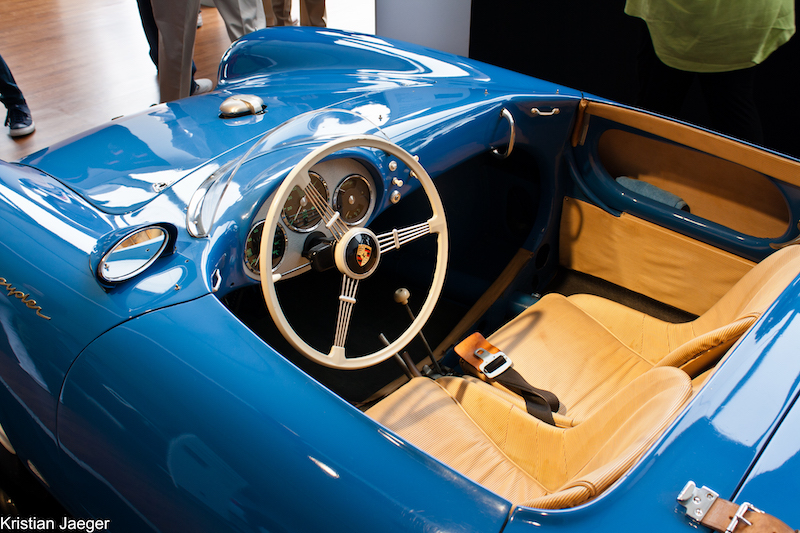
The second run of 550 Spyders all had this intriguing bit of frippery at the leading edges of the doors. As previously discussed, there were curled aluminum somethings riveted in the lower front corners, making a sort of Nabisco corner over the lower edge.
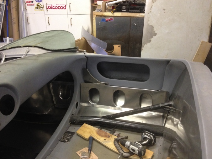 These took me like five tries to make to my satisfaction, and what I ended up with is still not quite right.
Above those, presumably to block any air intrusion through the door gaps into the open goddamn cockpit are these baroque rolled bits of vinyl around rubber tubes held in place by machined 1/3-round aluminum tubing screwed to the doors.* Looks something like:

So I cut off a bit of my wife's garden soaker hose, applied the grinder to some alum tubing and


*"Just why Porsche went to such lengths to trim out a race car is a mystery to me."
–Rainer Cooney, The Spyder Factory
Ed, regardless, you're doing amazing work!
Why did they go to such lengths? The only answer is they were GERMAN. Everything gets complicated when they are involved. They can't help it.
And as far as pedal ratio I was talking the relationship of pedal length to MC push point. So since you duplicated an existing ratio, I think you're good.
If the slave is still blowing bubbles you either have a leak in the MC or maybe one of the fittings somewhere is sucking air. I bled mine by myself with a broomstick through the steering wheel in 2004.
Well, I think I've finally diagnosed it...
Which is just freakin' beautiful.
Presumably I screwed up the throwout bearing somehow, either by installing it wrong or, more likely, by installing the wrong type. (Any other wagers?)
Either way, apparently it's time to remove the engine and transaxle again.
Nothing's more fun than that, right guys?
I guess it's just one of those days:

edsnova posted:Well, I think I've finally diagnosed it...
Pesumably I screwed up the throwout bearing somehow, either by installing it wrong or, more likely, by installing the wrong type. (Any other wagers?)
Either way, apparently it's time to remove the engine and transaxle again.
Nothing's more fun than that, right guys?
Some days... I had a similar moment when I realized that I hadn't even installed the throw out bearing on mine. Good luck!
Yeah I put one in. It's held in with wire clips, which I remember because it took me a minute to grok how they were supposed to work. Seemed to be the right style.
Anyone have any insight into this? I remember when I did Bridget's new clutch I had to omit a part of the new TOb that was made to fit both old and new style transaxles. Did that on the second try....
This trans is the old style so I figured I was OK...
Edit:
But of course the pressure plate is different. The pressure plate. The plate that came with the engine is late style, fingers, no collar. See below, circa 2:30

—which means the TOb can't reach it. CAN'T WORK. GODDAMMIT!
So that means I have to either
1. replace the clutch, or
2. buy and install a late-model conversion/upgrade trans seal/collar kit
either of which requires the whole friggin thing to come back apart.
I feel for you ED !! I think I have the record for engine R&I though. Only 11 times in 4 months ! Yup, wrong T/o brg, knicked input shaft seal, two blown oil coolers, oil pressure regulator piston jammed in, broken weld on T/O brg. release lever, leak on camshaft plug in crankcase. no spring on crank seal. A couple more that were optional when I was doing oil temp testing. Got pretty good at it ! Zipper's would have helped.
When I had the engine apart for the cam plug leak, I installed the Total Seal piston rings. That turned out to be a real plus.
Over the years, I've always heard a lot about problems with the clutch release system on VW's. It has always seemed like it involved the cable, the tube or the lever. I have often wondered why nobody came up with a steel rod from the pedal lever all the way to the lever on the bell housing. Possibly it would need a bellcrank where it comes out of the body at the center tunnel. Hydraulic systems always have their issues as well and I have never trusted them. Clutch cables in our cars are seemingly all a different length and therefore difficult to get a replacement that is correct. When we build these cars we have to seriously modify the floor pan, opening them up like a tin can to shorten them and get everything to work again when assembled. It seems like it wouldn't be difficult at that time to install a 5/16" (or even a 3/8") steel pull rod from front to back along with a non-reversing 1 to 1 bell crank at the rear to terminate it and then up to the clutch release lever with another pull-rod. This would eliminate the need for the Boudin tube as well. If done right, the bell crank could be drilled with extra holes to allow lengthening or shortening the stroke........Just a thought.............Bruce
Oh that sucks. It is just a ring that mounts in the pressure plate, not a lot of money either. But yes, a LOT of work. You may be able to support the engine and just slide the trans back. With a flywheel lock, it's six bolts to R & R the pressure plate and install the early ring for the early throwout.
Whoa. Something like this, Danny?
This may be the thing I set aside when I did the Bridget/Soob clutch. I wonder where I stowed it...
Yes, exactly that, Ed. It has a sort of snap ring that holds it in place from the flywheel side against the clutch fingers.
Bruce, I don't understand the dislike of hydraulic clutch mechanisms. They are very widely used and more reliable than those cables that are always breaking. I've had my fair share of many broken cables (3 on one Scirocco alone) over the years. Honestly the cable arrangement on early Spyders was a bit Rub Goldberg with the direction-reversing pulley.
I've had only two hydraulic failures. One was the slave in my 5000CS quattro. It was almost 20 years old at that point. The other was the Neal slave in my Spyder, which merely needed to be cleaned. If you flush the brakes and clutch fluid every two years as recommended it's a non-issue.
Ed's problem is one easily solved and is merely a parts compatibility/error having nothing to do with actuation method.
FYI, your Subaru Spyder trans has a master/slave arrangement.
Danny...As Tom Selleck said in the movie, Quigley Down Under..."didn't say I didn't know how to use one. I said I don't have any use for them". I've had hydraulic clutch actuators in several of my "project cars" and, as you said, I will in the next one as well. They are a very expedient way of getting the job done in a pretty good way but are more finicky. Especially when slight leaks occur. Many people, with limited experience, don't understand some of the critical aspects of how they work. Even though the system seems simple. One example comes to mind regarding piston/cylinder sizing of both Mstr.Cyl and Slave. Another is making sure the fluid lines are not in contact with severe heat sources such as exhaust pipes. In one system, the owner didn't remove the residual valve from the Master cylinder. Another one, the owner had too much angle on the push rod in the full extension position, limiting the release force and travel distance. Another, the slave was too far from the release lever and ran out of travel before the clutch was released. Sometimes it's just better to keep it simple if possible. As you said, you've had your fair share, and so have I, of clutch problems and I have concluded that a good solid mechanical linkage set-up is pretty fool proof for a long time. How it works is also easily understood by nearly everyone. In the end.....There is a place for hydraulic clutch systems but personally, I wish it were not so.
Speaking of Subaru Clutches. How do they compare to the HD units we use on a VW ? The one on my engine looks about the same but I'm not sure. It is made by Subaru and I believe it's used in a Subaru Forester..................Bruce
Mine is an Impreza, Bruce, and uses a cable.
Thanks Ray. Do you know the diameter of your clutch ? I neglected to ask them at Outfront when they changed out my flywheel and took back the Subaru-to-VW bell housing adaptor. One of the guys there said he thought the clutch assy was from a Forester so that wasn't a definite answer. I will have a hydraulic clutch release system in the Spyder (my favorite Ha ha ! ) ...............Bruce
I am not sure but the tranny type is an Impreza TY758 which has the clutch arm, pull or push I forgot but it works well with the cable and I like the tension on the unit so it works for me and that is what I prefer. IM makes a hardy cable for it I am told.
The ratios work quite well and I can row with it up and downshift with ease and it does not have a gap like my 4 speed 3:44 had on my old IM.
I hope you enjoy it.
BTW I am not sure on the diameter but the tranny details should allow you to find it easily as it is a stock flywheel and clutch pressure plate set up for a N/A 2.5L engine
FYI , OK build sheet is 4.1 final drive. TY758 donor (2009 onwards)
1st gear 3.454 2nd gear 2.062 3rd gear 1.448 4th gear 1.088 5th gear 0.78
Taking the Spyder apart from underneath so Cory and I can get the engine and trans out tomorrow.

I ordered the clutch ring thing and hope to get it next week. Will probably re-do the oil lines as well, because I just don't like 'em. We'll see when we can get the engine back in after that.
Also did a final adjustment on my fuel gauge sender before unhooking the battery.
Ray......Thanks for the info on your trans................Bruce
Removed exhaust, oil filter, lower engine mount nuts, fuel lines, wires and breather hoses. Still gotta do the diagonal breather, coil mount, starter, holy subframe thingy, engine cover, hook up the hoist hooks, take off the (painstakingly just adjusted) swingarm bolts, jack the frame, remove the wheels, calipers and (I guess) hubs (oh crap there's still oil in the trans)....
Ugh. I hate redoing things (he said as he rebuilt the ECU engine wiring harness). I think you've got me beat though...
Cory brought donuts, took the drive train out of my car and then stuck around another hour and a half cleaning my shop for me, basically.


Yeah, that guy.
Good luck finding your tools after Cory put them away, buddy.
Get that clutch sorted!
contraire, Danny: I'll be sorting and filing tools over the next few days. A chore that is very long overdue.
Also, check your text messages, pls...
IaM-Ray posted:
...FYI , OK build sheet is 4.1 final drive. TY758 donor (2009 onwards)
1st gear 3.454 2nd gear 2.062 3rd gear 1.448 4th gear 1.088 5th gear 0.78
Those are nicely spaced ratios, Ray; they'd be fun no matter what (or how big) the engine is.
@edsnova- looks like you and Cory had a good day!
It is a lot of fun but if I ever open it up I would change the tranny gearing to the following. What do you think.
4.1 R&P Proposed new R&P 3.9
1st gear 3.454
2nd gear 2.062
3rd gear 1.448
4th gear 1.088
5th gear 0.78 fifth gear to 0.735
tyres are 24.88 inches
TO conclude change the R&P 3.9 and the fifth gear to 0.73.5 5th gear
This would give you 2700 rpm at 70mph.
If you look at the calculator below, #1 is what you have (couldn't find a tire size that's exactly 24.88" but the 205/60-15 at 24.69 is very close). Ideally you want the rpm drop of each successive shift to be a little smaller- for general driving this takes the best advantage of an engine's powerband and makes the car easiest to drive (especially if the engine is smaller). With a Subaru engine there's enough power that it still all works- and no worries about slower fan speeds not being able to cool an aircooled engine properly at higher speeds. I would space out 3rd and 4th a little more so the drop into 5th isn't so drastic, but 1st through 4th acceleration must be fantastic! For canyon carving the larger drop going from 4th to 5th does put you at a little bit of a disadvantage, but if you really do like everything more or less the way it is I get that as well.
#2- Lengthening 5th gear makes the 4-5 drop even bigger, but again, if that doesn't bother you, then so be it. The r&p change doesn't change things much (for the money spent), so you have to make that decision.
http://www.teammfactory.com/ca...35/0/3600/3600/1/0/2
Now check out below- #1 is what you're proposing and 2 is what I would be tempted to do- lengthen 3rd and 4th slightly as well and now that (even bigger) 4-5 hole is gone. The 2-3 and 3-4 shift are still close enough that you won't lose much and when running with the guys in the mountains power in 5th is right there!![]()
![]()
![]()
![]()
http://www.teammfactory.com/ca...35/0/3600/3600/1/0/2
Hope this helps. Al
Did you look at that SB convertible or the KG?
Ok- fixed it...
Al, the solution for Ray is obviously a 6 speed LOL!
DannyP posted:Al, the solution for Ray is obviously a 6 speed LOL!
An available 6-er would be enough to get me to build one more time.
Thanks Al the ratios I have right now Are really nice and if I could just do the 6th and maybe the R&P we could have a cruising gear at 70mph of 2500rpm
So you could put a subie 6 speed but it is a few inches longer and you would need a cable shifter.
You probably would need to lengthen the body like IM-6 frames unless the cross member in the I M frame could be opened and somehow made stronger as you need 4 inches more .
Australia does it
Upholstery. Made the passenger door top today and went ahead and installed it with the front "roll" piece. Nothing—but nothing—is easy on this thing.

There's a 3/8-inch gap between the trim piece and the door proper at the top. The bottom (which no one can see) is nice and tight.

I ended up clamping the piece to close the gap, but I think I'm going to have to take it apart and reshape it.

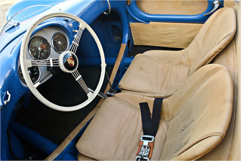
Again, the look we're going for:
My clutch part came yesterday so I'll probably turn my attention back to the drive train for a few days whilst pondering what to do with the interior...


Ed call me with your interior fabrication questions.
Corrected. Used a bit of windshield washer tubing. I'll stretch, glue and staple the material back over it tight and we'll be right there.

Separated the engine from the trans this AM and realized I was unsure of how exactly this clutch ring thingie attaches. My recollection from the old one is the flat coil spring affixed to the back of the ring has to come off to make the part come off; by this I deduce that installation will require my threading said spring back on from behind—after I remove the pressure plate of course.
Has anyone here done this job? Any advice appreciated.


Update: I did this and put it back together, tested the clutch arm this time with a big wrench. It works.
The clutch ring thing goes on like this:


Re-torqued the pressure plate to 20 ft-lbs
Married them back up. Quite pissed that a load of gear oil leaked out from the axle boots. The brand new axle boots. WTF?

Ah well.
Also finished the door top upholstery on the driver's side. 

vs
Continuing interior upholstery work. The rocker box covers are looking OK and I also put in the hold downs for the "emergency top." The replica shape meant I couldn't locate them exactly as original, but I doubt most folks will point and laugh.

as against


Continued upholstery work. Test fit the top of the firewall piece (chipped the paint! Grrr!). Stapled and glued the last (lowest) bit of velcro to it. Started making two filler pieces to fill small gaps in side of firewall just behind the doors.


Cut, bent, drilled and welded the "emergency top" mounts--they'll help pin the vinyl to the firewall at the sides. Primed them.

Test fit Knecht styler air filter. Had to grind small reliefs in the velocity stacks. OK.
@edsnova — this looks dynamite!
I feel your pain with the Vintage Speed Air Cleaners. I had to do the same with my velocity stacks. Pat Downs and I did this part together, and he was not impressed!
I used EMPI filters in there and removed that grey foam that came it with it; it seems to fall apart easily and seems highly suspect. If you need another set of EMPI filters, I have some.
Anand
Thanks, Anand. Think I'm going to use the filters from the other rig.
Meanwhile, I put the engine back in today, albeit loose.
I was going to wait for my new oil lines but there's no sign of them so I figured it's a sunny day so I'd get on with it.


Hopefully I'll find time to button it all up nice during the week.

Progress on the upholstery. All but done.

Now to hook the engine back up and get the dang thing running and registered!
One more...

vs

vs
Rub it in ED...... Just drove them...... Details didn't matter.... Poor fool that I am.
Beautiful!
Just a quick update: The engine is in solid now (there were complications) and I've got new nylon-braided oil lines and fittings ordered (after trying four different ways to re-do the oil lines.
I bolted the starter back in this am along with the breather tube and coil bracket, and re-filled the transaxle with gear oil.
Here's a sexy shot of my car's jack as test-fitted, followed by a pic of the same parts on 550-0073.


Ah, so THAT’s how those worked! Give me a long enough lever and I can more the world (or something like that).
I love the little touches like the leather belt on the jack. Beautiful work!
The jack works but it seems to want you to NOT set the hand brake or put the car in gear. The car seems to want to roll a little as the jack levers under it. It's a little scary to do it. I might get a small conventional scissor jack and stow it somewhere.
Meanwhile, I'll just note for the record...


I was wondering about that rolling up on that lever jack. That would be scary, especially around here, where a perfectly flat emergency roadside surface would be uncommon.
Awesome details though.
Small update. Oil lines redone (maybe for the last time?) and so I put oil back in the engine and bolted the exhaust back on. Weirdly, it's tighter to the frame than it was before, so I'll loosen all the nuts tomorrow and see if I can adjust it.
Still gotta test the clutch but now I can maybe start the engine to do that.

IF I can get clutch (wish me luck!) I'll be able to go ahead and tighten up everything— shifter cables, re-align the wheels, big axle nuts, etc. etc.—and then put the rear shocks, engine cover and various dust-excluding accoutrements back on the car. Then hang the driver's door, put the floor in and be at last ready for her close-up with the Maryland State Police and MVA.
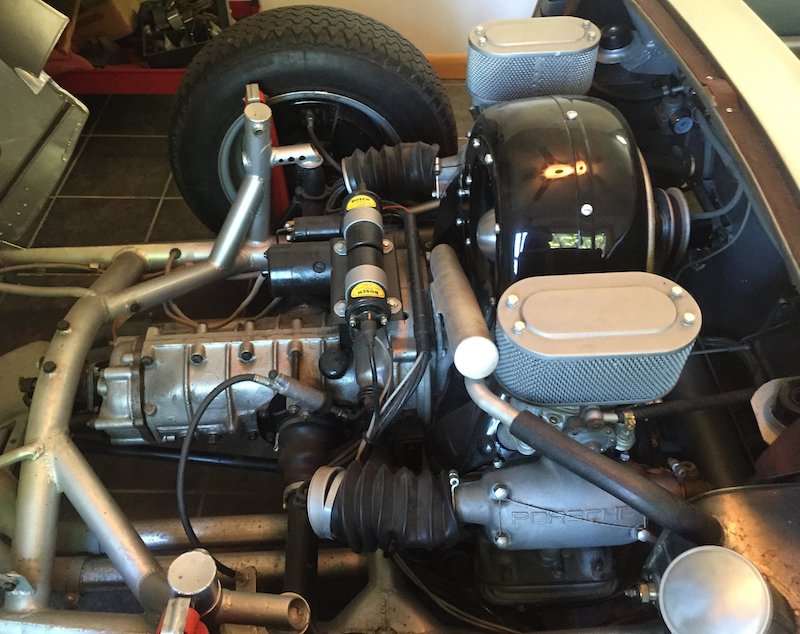
Gratuitous shot of 550-0054's open engine bay follows:
Beautiful work Ed !
Great progress, Ed. Good luck on clutch!
Tested clutch again this am. IT WORKS!
So of course I then hooked up the e-brake and then immediately pulled it and bent it cut it down and pulled the shifter to mod the e-brake mount to make it lower so it'll be more like an original. There is something really wrong with me.

I can lower the round mount thing about 3/4 of an inch to bring the top of it even with the top of the shifter housing, and lower the front of the handle the same to get it closer to the top of the bulkhead. This will make it more like they actually were and give the driver just a skosh more leg room. While I'm at it, I'll also add another mounting screw to the front "leg" of the handle to tighten everything up, since it was just a little wobbly before.
While I'm welding stuff, I also plan to make a stiffening brace for the pedal box up front, as I noticed just a little movement there as well when the brakes were getting pumped violently for final (?) bleeding. It's only about 6-7 inches to the back of the beam mount and there are already bolts in it for the sway bar, so it should be a simple matter to fab up a T with some angle iron and half-inch round steel, with a loop to bolt it through.
We are not worthy... Glad you have clutch and glad you're not being namby-pamby about building the beast close to original!
Ed will you be ready for Carlisle this year?
I think yes.
Ed, I really hope to get a ride in that magnificent beast if you bring it to Carlisle.
Same w/ your coupe!
Heck, I'll let ya drive it!
Screw you, Lane, screw you.
OK so here's an update with some stupid fabrication that no one is likely to see except for here.
I got my wife to help bleed the brakes like Danny said—hard pumps and such—and while she kicked those pedals I noticed just the slightest bit of movement on the front firewall/pedal bulkhead.
As many of you know, that item on a Beck or TR car is an eighth-inch (3/16 maybe?) steel angle plate welded between the frame rails, whose top rises several inches above the tops of the tubes. It's plenty strong enough, I guess, but then to make my clutch pedal more "realer" I sectioned mine and welded those big chunks of it back in with the 220 AC stick machine which, although a good job for me, probably did it no favors, strength-wise.
I could see it flexing, boys. I did not like that.
So I decided to make a brace tying the top of that plate, right where the clutch and brake pedals attach to it, to the lower tube of the beam, seven inches forward. Seems a good spot because it's also where the beam tubes attach to each other with that big channel piece that you'd ordinarily use to fix the beam to the frame head on a VW pan. Strongest spot on the front axle, I'd guess.
I designed a triangle brace V-ing from inside that channel (thinking I'd bolt it to my swaybar bushing mount) out to a bit of angle bracket I'd affix to the back of the bulkhead.
Then I started rummaging through my bucket-o-scrap metal hunks, CADing things out and shining a light up under there while trying to make more junk fit.
It's really tight up there in the space above the master cylinders and below the tank and steering stuff. Especially when you're trying to fit your hands in there with whatever you're trying to improve matters with.
So after simplifying and adding simplicity, I ended up with this.

The curved part rests on the lower beam just behind the channel; the tube is centered on the beam. The bottom nut is fixed and welded so the bolt turns to adjust the tension. The middle nut is there to give your wrench something to turn, since the bolt head's gonna be shrouded.
It fits parallel to the ground. I have a bit of heavy C-channel that bolts to the bulkhead with a couple 1/4-20s.

 Then I welded this sway bar bushing washer to the bolt head, to tighten up the fit in the channel.


I'll test fit it again tomorrow and, if it's good, drill small holes through the bolt head and the edge of the channel so I can wire it tight once it's adjusted. Not as good as a turnbuckle with a lock nut, I know, but I'm hoping this will be a one and done.
Ed, I hope you're having as much fun doing this stuff as I am watching what you are doing! I bet you're over 3 standard deviations away from the mean on the Welsh Figure Preference Test Origin Scale (highly correlated with creativity). Short version: you come up with the coolest solutions!
mppickett posted:Ed, I hope you're having as much fun doing this stuff as I am watching what you are doing! I bet you're over 3 standard deviations away from the mean on the Welsh Figure Preference Test Origin Scale (highly correlated with creativity). Short version: you come up with the coolest solutions!
No.
He (like other *ahem* pedants on this site) scores at least borderline on the Asperger's Scale. This stuff is 3 deviations past mean, for sure, and I mean that in the nicest possible way...
Stan Galat posted:mppickett posted:Ed, I hope you're having as much fun doing this stuff as I am watching what you are doing! I bet you're over 3 standard deviations away from the mean on the Welsh Figure Preference Test Origin Scale (highly correlated with creativity). Short version: you come up with the coolest solutions!
No.
He (like other *ahem* pedants on this site) scores at least borderline on the Asperger's Scale. This stuff is 3 deviations past mean, for sure, and I mean that in the nicest possible way...
There certainly are a few of us who need occasional reminders that everything doesn't have to be perfect! :-) Although, as Ed demonstrates perfect is sooo purdy!
Update: It's good.


I'll mount it in there tomorrow with a dab of silicone goop on the beam and lock washers on the nuts, and wire it tight.
A reminder: "perfect" would be if the thing didn't flex in the first place, like if I welded in proper gussets when I altered the bulkhead for the clutch pedal.
I think this fix qualifies more as an "elegant bodge."
I appreciate everyone's patience and encouragement over these past three years. It's the 11th hour of the build and my welds are starting to look "not totally incompetent," which gives me a feeling of great accomplishment and manliness.
And done. A well-spent 7 hours...
Are you tabulating all the hours you got in that In the whole world you got I just love Siri
I said build
1552.75 hours and many more dollars. The spreadsheet has 668 lines so far.
Nice to see the wire lock. That's the frosting on the 7 hr cake!
So I tried to like military press the pedal cages up and there's no play or flex at all in those anymore. They move with the car's suspension now.
I put the shifter and e-brake back in today, locked out the rear wheels and cranked the axle nuts to about 250 pounds. Looks-wise I think the interior's as good as it's going to get, in terms of fealty to the original cars.
This is 550-0018's interior as photographed from behind the driver's head.

And here's my car from a similar vantage point:

Steering wheel's a little smaller. Shifter is a little shorter. Shift housing is a little bigger. But it's in the ball park. I'm OK with it...

I want to try 420mm wheel myself that gives you the old car feel.
Very nice work, Ed. Very nice. I miss my old banjo steering wheel and may swap mine out for one some day.
I've got a 17-incher on Bridget and it's great but you gotta kind of slide around and under it. Not sure I could work with one that big on the Spyder.
Here's the common interior diagram from (I guess?) the original 550 owner's manual, next to my car. Switch gear is even pretty close. I've got 8 (lower) as pre-oil/Accusump and 8 (upper) as wipers (which are not installed), and 12 pops the hood latch instead of the oil cooler grill slats as original.


I am utterly amazed at what you’ve accomplished here, Ed. This is really something special.
It's a work of art.
Difference? What difference Ed. Awesome.
Absolutely stunning ! If time permits Connie and I will stop at Ed's to see this beautiful work of art when we're in Baltimore later in January.
Bloody amazing - that's all.
Yes. Definitely nailing the look. I seriously hope you have it come September. I'd love to see it parked next to mine in the Porsche Corral at LRP. Confuse all the arrogant ones......
DannyP posted:Yes. Definitely nailing the look. I seriously hope you have it come September. I'd love to see it parked next to mine in the Porsche Corral at LRP. Confuse all the arrogant ones......
Hopefully, if all goes right, that beautiful French Blue 550 will be in my garage come this September......I’m just waiting for 6 little numbers. (To match the 6 little numbers on my ticket)
👍🦌@Kevin - Bay Area is this a nice early Christmas 🎄 🎁 come early Sept.
Who's the faux-est one of all? New Award for Carlisle?
Here's a "problem area" on my car. If you squat down in the door frame and sight across the front of the seats to examine the shifter and e-brake handle you can really see how incorrect they are:

As compared to this shot of 550-0073 (The Al Special):


Looks great to me, don't squad down, problem solved and it will be just fine ~
Yeah, like Alan said, stop squatting down to look at it.
I like Alan's solution, Ed. Sounds like a winner, especially when you remember that most replicas are longer than the originals.
Supposedly these cars are about 4 inches longer and maybe 2(?) inches wider. It's kind of stunning when you look at how small they are and realize "yeah, too big tho."
You do realize, of course, that YOUR shift lever is topped with a "Manly-Man" shift knob - something that can be grasped securely in your hand whilst giving you the feeling that you are in charge as you power through the gears.
YOU are a motoring Ace, deserving of such a fine machine.
On the other hand, that "550-0073" special has a (yawn....) VW "People's Car" mushroom shift knob, the same as in my 1957 Oval Sedan and two million other "people's cars". That had 36 wimpy hp. And no heat (but plenty of exhaust fumes).
If anyone asks, just tell them that you have the same "special" shifter that they put onto the winning LeMans cars which was then removed and presented to the winning driver as a race souvenir. Yours was removed from a non-winning (DNF) car and it later appeared in a rather sketchy ad on "Bring a Trailer", where you won the bidding at $12,500.
That sounds very believable, Gordon; consider it done.
To explain my less-than-perfect frunk rendition I shall also endeavor to develop an outrageous story involving the necessity of fitting the FIA-mandated 60x40x20cm hard-sided suitcase under the bonnet in order to continue to qualify in the sports car class for sanctioned under-2 litre hill climbs on the continent after 1960.
In this car's context it makes excellent sense.
It's all in the details. Wow...
 That 0.5% of car enthusiasts that know the 550 will know the car is a replica based upon the proportions. But 1/2 of that group will still admire all the attention and time you have into your build. The other half of that group are total snobs, so who cares what they think?
The other 99.5% would think it’s real if you had an “8-ball” shifter knob on it.
One day, in the near future, I’d like to either make or buy (probably buy, because we’ll #idiot here) the shift knob from the 917.
Correct Kevin! And at this point anyone who knows what a 550 is (and what they sell for) will know it isn't real just based on the fact that it's being driven on public roads. But it'll be worth a second look anyway, I hope.
I always liked Lenny's spider shift knob. Similar to

^^ THAT! ^^
Is Wicked Awesome!
And Ed: Someone in the Beaufort, SC car club had a case with similar dimensions in the trunk of his '62 Corvette for car shows. When he opened it (usually just as cars were getting lined up and parked for the show) he had all the fixins for high-potency Bloody Marys (recipe from "Kathleen's Pub" on Bay Street) which, of course, got quickly passed around, so by the time the crowds arrived the club was in a party mood (read that, "pretty well lit"). The good old days....
Not that I am in any way endorsing such craziness, but those dimensions lend themselves to something better than tools or spares, don't-cha think?
edsnova posted:Correct Kevin! And at this point anyone who knows what a 550 is (and what they sell for) will know it isn't real just based on the fact that it's being driven on public roads. But it'll be worth a second look anyway, I hope.
I always liked Lenny's spider shift knob. Similar to
@edsnova Some PITA advocate might not like that 😎🎄
Yes, PETA can sometimes be a PITA.
I believe that those spider knobs are no longer available as it is illegal to kill them and cast them in resin.
DannyP posted:I believe that those spider knobs are no longer available as it is illegal to kill them and cast them in resin.
Nope, it's because the spiders are still ALIVE and trapped in the train. You can see mine wiggle a leg every once in a while. :-p
I actually measured and there's no way I could get an FIA-cert suitcase to fit in the front of my car. This will make the story even more complex and entertaining.
Clutch re-tested, Spyder script secured, screws holding the Autopulse fuel pumps set with permatex red, under-cowl vaccuumed and Wendler badges installed this morning.

Where the heck did you find the Wendler Badges? The Spyder Factory is making those from scratch.
@Gordon Nichols -- I think there are others making them -- Carey, for one, comes to mind. Carey hits them with some spray paint and gives them that antique look. Pretty cool!
Access to this requires a premium membership.
Supporting members have donated about $4.00 a month ($49.00 US per year) paid annually.
AUTO RENEW: You membership will auto-renew after 12 months. If you prefer not to auto-renew, you can cancel your premium membership at any time and it will remain in effect until the end of the 12 months. To cancel, sign in at SpeedsterOwners.com and navigate to: (Your User Name) > Premium Membership.
PLEASE NOTE: Your credit card will receive a charge from CROWDSTACK PAY, the payment processor, not SpeedsterOwners.com.