
 

Todd M posted:


...This is way off topic, but the point is that y'all are helping me tremendously with my coupe build, and if anyone has a question about repairing or improving something on their house, please feel free to ask me...


Not off topic at all, Todd.

Ed (remember him?) is a British car dude. His other car is an MG-TD replica. Which isn't too far removed from that other Jurassic British car - the Morgan.

Which, as it happens, relies heavily on laminated wood forming.

Here's a laminated ash fender fresh off a recent production line.

MorganFender

And here's the 60-year-old form they still use to bend every one. It's not the original from 1920, of course. That dodgy piece of work wore out in the 1950's, after only about 35 years of service.

MorganForm


Attachments

Images (2)
  • MorganFender
  • MorganForm

Most of you guys are better than me at everything. Here's Bridget's dodgy dash board I made a few years ago with some marine plywood and 1/8-inch blanks of mahogany and tiger maple I mail-ordered from Woodcraft. Cut it all up on a table saw and glued it together with some furniture epoxy. 

I still kind of like it.

Plus I equipped a proper British "Gentleman's Emergency Kit" in the glovebox.

Looks good Ed !                                                                                                                        Tommy Martin (your painter) has done about 2/3 rds of my cars including speedsters,  T' Buckets,  a couple of tubbed pick up truck, car trailers and a metal Futon couch frame :~)

Alan Merklin posted:

Tommy Martin is retired previously owning a huge body shop business . He previously did insurance work, custom motor homes tour bus's, fleet and custom tractor trailers... and a lot of my projects. Tom now has a shop at his home in in St. Thomas PA  (1 hour south of Carlisle) pm me for his phone number. 

St. Thomas, PA?  Guess I will be looking a bit more local.

@arajani that's way too kind coming from someone who knows what these firewalls are supposed to look like. Thank you.

I've worked up a story to tell, though, depending on the context. I might tell someone I got the car in pieces (which is of course true) out of a pole barn in NW Connecticut (also true) and did a lot of aluminum and body work on it (again, very true) and that "when I got it the firewall was bulbed-out & twisted up all kinda impossible stupid ways and it took me dozens of hours to pound it mostly straight."

Obviously a very terrible lie, but in the right ear could be worth telling, just for the reaction. 


Car is back in the garage

Cory came by today and helped me do some stuff to get it ready to put the dang engine in. Cory is a great human being, people. We hung both doors to check gaps and straightness, and I'm liking it fine. 

Then we took off the clam and the hood to facilitate final assembly. The doors will probably come back off too while I work the wiring and then the upholstery....

On a side note: Bridget has a blown head gasket, so currently I have two excellent cars for Carlisle, neither of which is likely to be ready for the show. Oh, the irony!

Wish me luck, boyos!


Ed, yeah great paint, great gaps, great paddle shifters, but wha... the Subie blew a head gasket?

The 200,000 mile minimum set-it-and-forget-it modern solution to old-school unreliability just went and blew up?

What's the lesson here? You put an engine - any engine - anywhere near something that even looks like a British car and it inevitably goes all British on you?

Did you torque the head bolts with Whitworth spanners?

WTF?


Re: Bridget

I drove the car about two miles on Wednesday night to the drug store and noticed the temp gage wasn't coming up. It was laying on 90 as I crossed the mile mark. Usually by then it's well off the peg. 

Dang Smith's dual gauge, I thought. This is the kind with the tube fulla gas and the bulb at one end you stick in the coolant, and the tube inevitably kinks somewhere and leaks the gas out and makes the $200+ gauge be no good. (You know they're good when they leak oil from the capillary tube onto your right knee). 

Anyway I got my nephew's birthday card, got 3/4 home and the needle just got to about 120. That's when the green light came on, indicating the fan was working. That worried me because the fan should not have needed to go on, and also because the light was extra bright, meaning that the Suby temp sensor was reading about 210-220. Which is unpossible in that short a trip on a mild spring evening.

Got home and felt the radiator, which was cold. Bad news.

Probably I screwed up. A few weeks ago it was nice so I rolled her out of the garage, checked the oil, started her up and took my wife to Ritas for gelatis. Nice. No problem.

What I did not do was open all the bleeder screws in the cooling system first. 

If you ask David Stroud about this, he will tell you stories. OK, he'll tell you stories anyway, probably, but this is an important story: Always open the damn bleeder screws before operating a Suby-powered Plastic Clown Car that has been parked for a long time. Always.

So I probably had a bubble in the system. They can and do develop over the long winter. The bubble probably made its way to the worst possible spot, somewhere in the left head. Air there means a hot spot forms, and pretty soon, with the extra expansion, you've got blown head gasket.

From there you just get more bubbles: the combustion gasses blow into the cooling system, displacing more coolant, pushing it into the overflow tank. And then pushing it out of the overflow tank.

Next morning I bled the air out of the system. It needed it. Then I ran the car a minute to see if the gauge would work. I was hoping it wouldn't: hoping the gauge was bad. Or hoping in the alternative that the bubble had been where the gauge bulb was, and now that was fixed and it would work as normal. After about 15 minutes idling it went to about 120 again and then the fan came on. Crap.

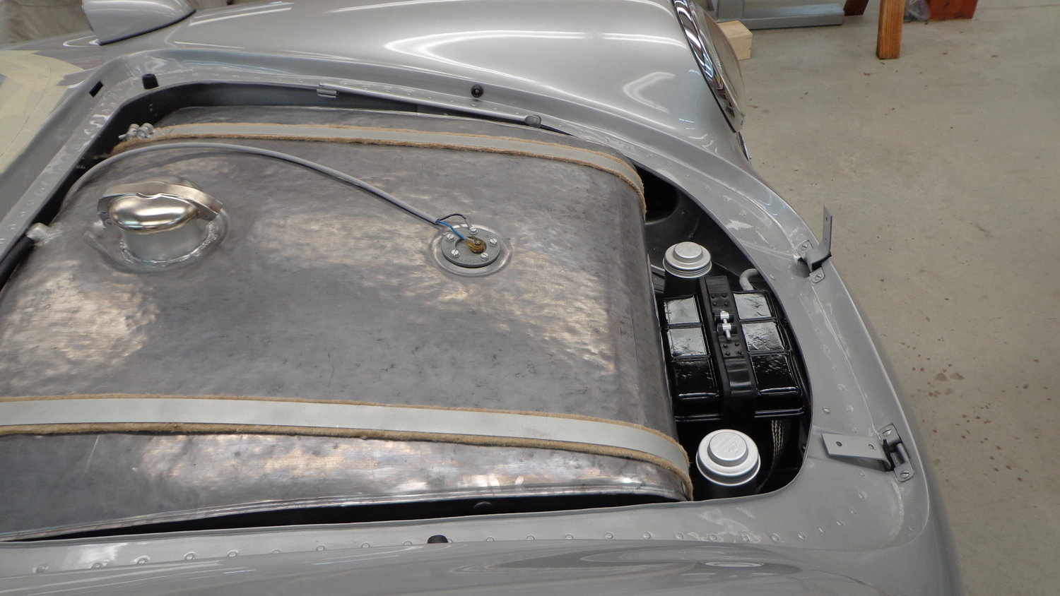
Now there was coolant dripping out the front. Checked all the hose connections--all good. Traced it to the top of the overflow tank. 

OK this was bad but it's not conclusive: maybe the thermostat was stuck closed. Hot coolant was expanding out of the top of the engine and trying to make its way to the radiator, but the thermostat wouldn't let any cold coolant in from the bottom like it should, so the rad stayed cool and the overflow tank overflowed.... Not likely, but oh-so-much-better-an-option, car-fix wise. On Friday I pulled it out and tested it on the stove. It works. 

So that leaves head gasket.


Stan Galat posted:

Bummer on the MG. The description doesn't exactly sell the Subaru as an awesome, final answer "get it and forget it" powerplant. We pick our poison, I guess.

Every platform has it's issues for sure.  In this case, the thermostat being stuck half way might be the issue also air is a big problem sometimes due to the length of the piping in the speedster especially and if you have multiple rads like I do it adds to the issue.  Subaru head gaskets were redesigned by the factory to handle the hot temp that happens when you stop the engine and then the temperature can climb in the head as the water/antifreeze boils... I use Evans cooling to prevent this.  In any case you could lose fluid do to the expansion and eventually end up with an air lock or bubble that you will chase... Moral of the story is that every spring bleed the system as a prevention... 

Oh yeah, it is not in the sales manual but it is part of the subie poison pill on our location of an engine... 

Advantage, the torque curve is awesome. 

Ed, do you have two evaporation tanks?  

You will note that turbo cars have two tanks to prevent the small loss of fluid that eventually develops air pockets, BTW and N/A have only one.  

My engine guy is installing a second tank on my car this Tuesday to eliminate continual evaporation that occurs due to the design of our cars and our systems eventually giving issues like Ed is living.


Thanks Guys ! This is new info for me ! I appreciate that you posted this. Being a Suby owner (not yet driving it) these are need to know things for me. Question : If I leave my sub sit for say 2 weeks to a month, is it necessary to bleed the cooling system ? Are these bleesers part of a sub or something I need to install ? My engine has a little stand-off tank now that Outfront installed (see photo). Is that sufficient ?.......Bruce

Attachments

Images (1)
  • IMG_0602: Stand off tube at top-left

Well I am sure once installed and the length of the hosing known your builder should install bleed valves at the high points where the air bubbles usually move to.  This would facilitate the bleeding and I usually do it at the beginning of the season.  A second tank may or may not be necessary if the system is fully sealed. 

I think what is to note here is that every set up needs to be worked through in the custom car field and every new car you get has nuances and maintenance that you have to learn about and fix and then schedule.  There is no panic in the Aircooled world and none also in the Subie just differences in what needs to be done and also the frequency of maintenance.

Ed,  Even if your thermostat tests OK, a replacement is cheap and good insurance.  Someone likely used that engine as a DD before your application and the t-stat has likely opened and closed thousands of times.  If you don't use a Subaru t-stat, make sure that your replacement has a jiggle pin, and that you install the pin at the upright 12:00 position to allow a slight coolant bypass until it opens.

Last edited by Jim Kelly
David Stroud posted:

Instead of hi-jacking Ed's excellent thread into oblivion, how about some interested party open a new thread and we can contribute dedicated info there ?   Please... ?  Bruce...Todd..you'd be likely suspects to start such a thread. Thanks.

Ed started the conversation regarding the cooling troubles he had with Bridget's head gasket. This seems like the natural place to discuss it between updates on the Spyder build.

Robert M posted:
David Stroud posted:

Instead of hi-jacking Ed's excellent thread into oblivion, how about some interested party open a new thread and we can contribute dedicated info there ?   Please... ?  Bruce...Todd..you'd be likely suspects to start such a thread. Thanks.

Ed started the conversation regarding the cooling troubles he had with Bridget's head gasket. This seems like the natural place to discuss it between updates on the Spyder build.

As you wish, Sir. Sorry for the intrusion.

David Stroud posted:
Robert M posted:
David Stroud posted:

Instead of hi-jacking Ed's excellent thread into oblivion, how about some interested party open a new thread and we can contribute dedicated info there ?   Please... ?  Bruce...Todd..you'd be likely suspects to start such a thread. Thanks.

Ed started the conversation regarding the cooling troubles he had with Bridget's head gasket. This seems like the natural place to discuss it between updates on the Spyder build.

As you wish, Sir. Sorry for the intrusion.

In retrospect I see the error of my ways. At least Todd and Air Cooled Bruce were asking for conversion advice on Ed's excellent build  thread and I thought It might be  prudent and more beneficial to ask for advice on a new, separate thread where the conversion info gained might actually be archived and helpful for others in the future. Please Todd and Bruce, I was not centering you out but just trying to help in a future informative thread. I won't bring up the idea again. 

Last edited by David Stroud IM Roadster D
Jim Kelly posted:

Ed,  Even if your thermostat tests OK, a replacement is cheap and good insurance.  Someone likely used that engine as a DD before your application and the t-stat has likely opened and closed thousands of times.  If you don't use a Subaru t-stat, make sure that your replacement has a jiggle pin, and that you install the pin at the upright 12:00 position to allow a slight coolant bypass until it opens.

Thanks Jim (and all). I replaced the T-stat with a proper OEM unit when I did the conversion in 2014; also the water pump (cast impeller) and then the head gaskets (Fel-Pro) and head bolts. The T-stat now has three seasons and about 3,000 miles on it and is fine. It only fits in the housing one way and, yeah, there's a little hole in it with a pin. 

There's one overflow tank in the car and it's in front.

The system works if I do the bleed procedures. I failed to do the procedures and this is what I get.

I tidied up the shop today. 

Cory was there yesterday and we all know he keeps his garage like a damn operating room. Mine looks more like the back yard in Sandford and Son.

So I put some tools away, threw away a bunch of boxes. Set things up so I could actually reach the Spyder engine which is still bolted to the pallet Carey delivered it to me on two Carlisles ago. 

Pulled the valve covers off the engine to have a look. Very clean and nice in there, and the rockers all seem to be rocking about a half inch when I turn the crankshaft over. Seems right.

IMG_2674

Pulled the clutch off to check it. With a claimed 1200 miles total, I figured it would be fine. And so it is.

IMG_2675IMG_2676

I  scrubbed the flywheel and pressure plate with a scouring pad, then rinsed with brake clean to remove any gunk. The machinists ridges are still present.

Then I cleaned the threadlock out of the holes, centered the friction disc with the centering tool and torqued the pressure plate back on, 20 ft-lbs or so. IMG_2678IMG_2679

I'll break out the CB Performance Black Box software this week and see if I can get it on my work laptop. I might install the engine and see if we can get things running first before messing with the disty. 

Haven't done the heim joints to the linkage yet either. But that's not hard to do with the engine in the car....

Attachments

Images (5)
  • IMG_2674
  • IMG_2675
  • IMG_2676
  • IMG_2678
  • IMG_2679

"I once straightened up my former PA shop only to discover a plethora of things I didn't know I owned."

I'm going to go through that again, soon, when we clean out my late brother's shop.  He built extreme horsepower snowmobile engines for the race crowd in the Northeast and had a nicely set up shop in his house basement to build them.  While he died a few years back, his wife hasn't touched the shop, other than getting rid of the torches and welders because of the big gas bottles on them, and it looks like he just stepped out for coffee. That's going to be a big deal to clean out, especially for the Hardinge lathe and Bridgeport Miller.  Both of those took four to six of us to move them in there.......

edsnova posted:

I tidied up the shop today. 

Cory was there yesterday and we all know he keeps his garage like a damn operating room. Mine looks more like the back yard in Sandford and Son.

So I put some tools away, threw away a bunch of boxes. Set things up so I could actually reach the Spyder engine which is still bolted to the pallet Carey delivered it to me on two Carlisles ago. 

Pulled the valve covers off the engine to have a look. Very clean and nice in there, and the rockers all seem to be rocking about a half inch when I turn the crankshaft over. Seems right.

IMG_2674

Pulled the clutch off to check it. With a claimed 1200 miles total, I figured it would be fine. And so it is.

IMG_2675IMG_2676

I  scrubbed the flywheel and pressure plate with a scouring pad, then rinsed with brake clean to remove any gunk. The machinists ridges are still present.

Then I cleaned the threadlock out of the holes, centered the friction disc with the centering tool and torqued the pressure plate back on, 20 ft-lbs or so. IMG_2678IMG_2679

I'll break out the CB Performance Black Box software this week and see if I can get it on my work laptop. I might install the engine and see if we can get things running first before messing with the disty. 

Haven't done the heim joints to the linkage yet either. But that's not hard to do with the engine in the car....

Feeling the excitement for you Ed. The end of this build is getting close and the Spyder is looking pretty nice. When it's all done a walk around video showing all of the "correct" replicated parts would be a real treat.

Bob: IM S6 posted:

"I once straightened up my former PA shop only to discover a plethora of things I didn't know I owned."

I'm still looking for my plethora.  I know it's in my garage somewhere...

Ok, I choked on my breakfast!

@edsnova wrote- " I might install the engine and see if we can get things running first before messing with the disty."

Those are wiser words than you realize, Ed! Trying to change the distributor before having the engine up and running (and in a happy state of tune) is asking for trouble.

Yoda out (but back you know I will be- for now a garage and more holes to drill awaits me, yes it does!)

So with the engine cover off, getting ready to remove the transaxle to mate it to the engine, I pulled off my rear spare tire mount/subframe and found my home brewed shifter linkage under that.

IMG_2680IMG_2681

Danny P. advised me like a year ago that the little nubby thing bolted to the crossmember next to the trans was a bad idea, since I had part of the shift linkage attached to the trans and another part attached to the thing the trans is mounted to with rubber (urethane, actually) biscuits, meaning they would not move perfectly together. 

I was gonna try it my way and see how it goes but, looking at it yesterday and realizing no one does it my way, I decided to re-do the left-hand bracket as something attached to the trans itself. 

IMG_2683

CAD first...

IMG_2684

IMG_2685IMG_2687IMG_2689

IMG_2692IMG_2695

IMG_2698IMG_2701IMG_2704IMG_2706

Getting close now; just got to complete the reinforcement tab and weld it on, then clean and paint it.

After that I can take the wheels off, put the back of the car on a dolly, remove the transaxle and see if I can find the right bolts to attach it to the engine.

From there it's a simple matter of assembling the engine crane, chaining the drive train to it, rolling the car back a few feet and hoisting it into place.

Attachments

Images (13)
  • IMG_2680
  • IMG_2681
  • IMG_2684
  • IMG_2683
  • IMG_2685
  • IMG_2687
  • IMG_2689
  • IMG_2692
  • IMG_2695
  • IMG_2698
  • IMG_2701
  • IMG_2704
  • IMG_2706

Yup, “Cardboard Aided Design”.   What many of us do when we don’t have access to fancy computers and 3-D printers.  Just get out the cardboard or, if you’re really cool, foam-core (Personally, I am not really cool).

Nice job, Ed.  That looks like it makes more sense and won’t get wonky as the engine/transaxle moves under load.  

Piperato was right.....again!

Finished the bracket this a.m. and hung it up for paint. It fits perfectly and has the stiffness it needs to do what it's supposed to. IMG_2714IMG_2712IMG_2709

Can I just say that having a bucket of scrap steel and a little wire feed welder has changed my life immensely for the better? Just a few years ago—like when I was putting the Suby in Bridget—I could not do half of the things I do these days as a matter of routine before breakfast. 

@ALB right: one more hole. I'd left it out because I wasn't yet sure how/where the reinforcement bit was going to fit.

Attachments

Images (3)
  • IMG_2714
  • IMG_2712
  • IMG_2709

David...Thank you for your comments and feel free to make them as you see fit. As I get further into my new build I'm sure I will have a lot of questions. A question I have right now is this. Since the "highpoint of the cooling system' looks like it will be this aluminum tube with the radiator cap on top on it, that will be  the highest point on my cooling system (radiator included). It seems that this would be the place to attach a coolant recovery system tank with a small hose to that overflow tube just under the filler neck. I understand that there may be some high points along the systems plumbing that may need air bleeds as well and those will need to be addressed at some point. Anyone care to tell me I'm on the right track ?........Bruce

aircooled posted:

David...Thank you for your comments and feel free to make them as you see fit. As I get further into my new build I'm sure I will have a lot of questions. A question I have right now is this. Since the "highpoint of the cooling system' looks like it will be this aluminum tube with the radiator cap on top on it, that will be  the highest point on my cooling system (radiator included). It seems that this would be the place to attach a coolant recovery system tank with a small hose to that overflow tube just under the filler neck. I understand that there may be some high points along the systems plumbing that may need air bleeds as well and those will need to be addressed at some point. Anyone care to tell me I'm on the right track ?........Bruce

I am glad you asked, and am also waiting for an answer.

aircooled posted:

David...Thank you for your comments and feel free to make them as you see fit. As I get further into my new build I'm sure I will have a lot of questions. A question I have right now is this. Since the "highpoint of the cooling system' looks like it will be this aluminum tube with the radiator cap on top on it, that will be  the highest point on my cooling system (radiator included). It seems that this would be the place to attach a coolant recovery system tank with a small hose to that overflow tube just under the filler neck. I understand that there may be some high points along the systems plumbing that may need air bleeds as well and those will need to be addressed at some point. Anyone care to tell me I'm on the right track ?........Bruce

Bruce..Amigo....Loud and Clear Now....this is ( we're on ) Ed's thread about his build and we're wasting his space. If you want info ( from me ) about a homebuilt liquid cooling system then YOU start another dedicated thread. Please.  I'll work hard to help you. Comprende ?  Last call

Last edited by David Stroud IM Roadster D

The worst I ever did was while installing a 3 sp manual in a car. I was laying with my head up towards the front of the car and the trans on my chest.  This way I could see when I had the input shaft going into the T/O beg and the clutch disc. At first you have to tilt it lower in the back to slide it in. I had already filled it full of 90wt lube thinking it's easier to put it in now rather than after the trans is in.. Since the drive shaft was out a lot of the 90wt ran out. I was skinny then, my Levi's were loose at the waist band and it was cool not to wear underwear then so all the nice warm 90wt ran down into my pants and all down around my nuts. Since it was warm I didn't feel it until I got the trans in and crawled out from under the car. What a sticky/smelly  mess to clean up !  I never was able to wash that smelly lube out of my pants so I had to throw them out......Bruce

Ah, transmission woes.......

After a few years, my CMC Speedster build was going very slowly and my wife kind-of got tired of waiting (and took some pity on me) so she found a really spiffy looking red Austin Healey 3000 right in our neighborhood.  We bought it.

It was in better than OK shape, but the overdrive was a lost cause, so I drove it home and decided to pull the OD to get it rebuilt.  Everything I read “on the Internet” told me it was way easier to pull the transmission and OD together as a unit, so I pulled the seats, carpets, bellhousing cover and floor panels (they are all easily removed), got a jack under it and removed the mating bolts.  Then, my son came home from college for the weekend and we decided to pull it out together.

We chose to use a pair of chains, slung under the transmission and we stood up on the sills of the car (doors way open) thinking that we could just lift it out enough to sit it on a sill, then remove it.  That was the plan.

No where, on the Internet, does it say, “Caution - This gearbox was originally designed for a tractor and weighs about 125 pounds.  No where.  

We start tugging and pulling, muscles bulging, vertebrates cracking, lots of grunting, veins turning red in our necks and foreheads, but the gearbox barely moved.  It probably took 30 minutes of straining (there may have been a few choice swears used) to finally get it moved back and freed from its’ comfy spot in the chassis and by then we were both wasted.  We finally had it on a sill and moved around to lift it up and moved to the shop floor to remove the OD.  

My son looks at me and says, “let me know when this is ready to go back in so I can find something to do at school instead, ok?”


Looking great, Ed.

I'm surprised you're using a Crispix box in the engine compartment, though.

Crispix wasn't introduced by Kellogg's until 1983, and so couldn't have been tossed aside by a mechanic or used for cardboard aided design in the 1950s. The Ralston Purina products that Crispix was developed to compete with, though, were around since the 1930's, so would be much more period correct.

I know, I know, go try to find an original Ralston Purina Rice Chex box today - unobtainium since they were bought out by General Mills 20 years ago, but it's details like that that make all the difference.


Sacto Mitch posted:


Looking great, Ed.

I'm surprised you're using a Crispix box in the engine compartment, though.

Crispix wasn't introduced by Kellogg's until 1983, and so couldn't have been tossed aside by a mechanic or used for cardboard aided design in the 1950s. The Ralston Purina products that Crispix was developed to compete with, though, were around since the 1930's, so would be much more period correct.

I know, I know, go try to find an original Ralston Purina Rice Chex box today - unobtainium since they were bought out by General Mills 20 years ago, but it's details like that that make all the difference.


Mitch you are my target market.

I use Unibits, the next step cleans holes nicely.

Ed, those two bottom transmission mount bolts are the bane of Spyder life. Easier to get to when the trans goes in first, then install and tighten. Then goes in the motor, but that's in my car with no torsion bar. I can see why you did it your way.

Do yourself a favor and weld an O2 sensor bung in your exhaust where the two mufflers merge by the tailpipe for tuning purposes.

Gordon Nichols posted:

They always look lighter when still attached to the frame horns.  Get them out onto the floorand suddenly they weigh over 80 pounds.  Still, lighter than the engine.   

Before I disassembled the late model single side cover (I wanted the case with it's offset top webbing for my Berg 5) transaxle I weighed it on the bathroom scale- 72 lbs. I'm sure a swing axle trans, minus only drums and axle nuts must come in at around 95 lbs. 

14 hours this weekend and almost no progress. Looking for new bulb sockets for the brake/running lights. Broke one of the lights trying to remove it after putting it on. (Fixed; they're just silicone glued). got no joy testing circuits with the battery in and grounded—power at the light switch at least... Hating my crimp connectors as you can just barely squeeze the shrink tube over them (and only then if you cut the ends off them before crimping). 

I mean dammit all to hell. IMG_2792IMG_2784

Good news: Vred Sprint Classics came yesterday (the day after I ordered them) so they'll be going on the V-190s tomorrow morning and the spare tire will be mounted as well. So at least I'll be able to cross that off my to-do list.

Attachments

Images (2)
  • IMG_2792
  • IMG_2784
edsnova posted:

14 hours this weekend and almost no progress. Looking for new bulb sockets for the brake/running lights. Broke one of the lights trying to remove it after putting it on. (Fixed; they're just silicone glued). got no joy testing circuits with the battery in and grounded—power at the light switch at least... Hating my crimp connectors as you can just barely squeeze the shrink tube over them (and only then if you cut the ends off them before crimping). 

I mean dammit all to hell. 

Hey Ed, it still looks brilliant even if some of the lights aren't on yet. I sprang for an upgraded crimper a few months ago when I was laying out the harness. I still hate it, too. Good luck

Mike

Vreds on V-190s (plus a steel spare with an older Federal). Mounted and balanced, ready to go. This is Chris, my tire/wheel guy. 

IMG_2795

I also put in an application for a Carlisle feature spot, in the hut. They want all kinds of pics for this and advise "plain background" and "good light" and obviously they assume the car is, uh, erm... assembled for all this. I uploaded some closeups of some of my talking points (more than 50 unusual Spyderesque details by my count) and emailed  Ed to state my position.

If they green-light me I'm bringing the Spyder, probably on a trailer. 

If not, probably not. She won't have any kind of top and probably the tonneau won't be right by then either so if there's no covered showcase spot I'll pull Bridget's engine and try to get the head gaskets replaced instead. 

Attachments

Images (1)
  • IMG_2795

Temporary trailer queen, I hope.

Steering shaft is in and adjusted (with a BFH) for proper length and gap. Hey does anyone have a spare steering shaft nut? I had two when i checked a few months ago and now both've gone missing. DM me if you can mail me one.

I keep plugging in wires and I still have nothing by way of operable electrical accessories. 

Lotta what i assume are ground wires aren't attached to anything yet though, so I'mma put the wheels on her and lift her up and take the floor off so I can get my grounding bus squared away.

IMG_2800

Also gotta put the clam back on and check to see if the engine fits under it. Looks a little bit high where the pipe comes off the top of the fan shroud. I don't recall anyone ever saying the DTM Type 1 shroud doesn't fit a Spyder. Does anyone know for sure it doesn't?

Attachments

Images (1)
  • IMG_2800
edsnova posted:

IMG_2800

Also gotta put the clam back on and check to see if the engine fits under it. Looks a little bit high where the pipe comes off the top of the fan shroud. I don't recall anyone ever saying the DTM Type 1 shroud doesn't fit a Spyder. Does anyone know for sure it doesn't?

If it doesn't, I don't wanna know about it. That shot of a DTM in reverse looks suitably excellent to me. Really stupid-cool.

Ed, some cars will have that top oil cooler hose tube hit the bottom of the clamshell, some not. Lenny's does not hit on his type4 powered Vintage with DTM. I think if it does hit you can flatten it some.

My 911 fan ring used to hit the clamshell under extreme conditions, like banging the next gear very hard, until I installed a stiffer rear trans mount and a transmission strap. There is no movement any more, thankfully.

So you have no working electrical because it's messed up or because you have nothing hooked to the ends of the wires?

Thanks, Danny.

Wires are not all hooked up. I'm trying to get front lights first for that small victory feeling but the car's fighting me.

What bulb sockets do y'all use for the parking/brake/signal lights? The ones I got fit loose and I haven't been able to source more than one (long discontinued) that fits tight. (And yeah I bent the tabs some).

Holes in mine are 1 1/8 inch. 

Update on the Week Of Struggles. Thursday night: IMG_2810

And this morning.IMG_2812

Also greased up and installed my parking brake cables and then broke one of them while reinstalling the caliper. IMG_2809

Also, Summit emailed to let me know one of the fittings I ordered can't ship until May 6. Dang! I knew I should've ordered from Allit.

But I did find several steering wheel nuts so at least there's that.

Attachments

Images (3)
  • IMG_2810
  • IMG_2812
  • IMG_2809

Are you at all concerned that welding on the sway bar will weaken it?  I would be concerned that you will change the temper of the spring steel that was used to make it.

Years ago, I read about some guys that cut 2-4” out of stock VW sway bars to use with narrowed beams, but the bars broke in the heat affected zone.

There IS a procedure for welding “spring steel”.

Usually the parts being welded are pre-heated in the area of the weld (for depth of weld penetration) but this isn’t always necessary.  The act of welding will anneal the metal at, and immediately around the weld joint, causing the metal to soften (that’s where and why the joint will fail, just off to the side of the weld intersect).  Often, a welded piece will suffer another break later on, not precisely at the original weld joint but off to the side (where it was softened).  The weld itself is usually harder than the original metal.

The way the newly welded joint is made hard again is to broadly heat the newly welded area to a specific temperature or color (most heat treaters go by the color of the metal) and then quickly quench it in oil to rapidly bring the metal temperature down and that process re-hardens the metal.  But this is a relatively precise process to get the hardness that you want in the finished spring steel piece (sometimes a durometer is used).  Too hot makes the metal very hard but brittle and will more easily break.  Not hot enough makes it softer and it will bend/break.  The usual process is weld the ends onto your bar, then heat the entire bar to a specific color, then quench the whole bar in an oil bath.  That will make the whole thing the same.

IIRC, there are special welding rods for welding spring steel.  Your local welding supply shop should be able to help with what you need. 

Last edited by Gordon Nichols
LI-Rick posted:

Are you at all concerned that welding on the sway bar will weaken it?  I would be concerned that you will change the temper of the spring steel that was used to make it.

Years ago, I read about some guys that cut 2-4” out of stock VW sway bars to use with narrowed beams, but the bars broke in the heat affected zone.

Yeah which is why I'm only welding on the last half inch of each end of the bar. If I embrittle the last inch or so (which is unlikely) the rest of the bar should still work as intended and the chances of the bar breaking are about nil.

Latest:IMG_3081

I test-fit the bar with the ends today, then cut about an inch off each end, re-slotted the ends and tacked these on to re-check how the proposed end links fit.

IMG_3077

Since my brackets on the lower trailing arms were designed for something else, I might re-make the piece that attaches the heim joint to the suspension.IMG_3078

Looks like I could just strap/clamp a piece of angle iron to it . . .

Attachments

Images (3)
  • IMG_3081
  • IMG_3077
  • IMG_3078
Last edited by edsnova

PS: In theory, I track Gordon's explanation of how the metal responds to heat. He has it about right, according to what I learned in school.  That said I have zero experience with this, so could give no practical help as to how to do the heat treat, nor whether the result you have here would in fact be either too weak or too brittle.

And: your welds look pretty good to me.  Practice makes perfect, I'm thinking.

Not sure an anti sway bar would be considered critical, but maybe.  If it broke or cracked and maybe fell off, methinks the car would still steer. 

My frame modification to allow flat towing was dreamed up by me, but was executed by a professional welder who is more artist than mechanic.  My job was pretty mundane:a  frame out of angle iron and plate.  But it was done perfectly. His real work is on hot rods, mostly custom headers and pipes.  Mostly stainless, very complicated and as I said, works of art, really.  Short of story: a truly good welder is a hard thing to find.

Guys. 

The bar is like 7/16ths diameter but remember, it's not butt-welded. I slotted it and then notched the plates so they snap together.

 IMG_3051IMG_3050

This does two things: 1. it creates a kinetic hold between the parts, independent of the weld. 2. it narrows the welded edges on the bar to less than the thickness of the attached plate.

After fitting them I beveled the edges to give a little undercut for the wire feed. And remember the scale:

IMG_3085

This is 3/16 mild plate. It's right about the max of what a flux 110 is supposed to be able to handle in one pass. It's handled.


Attachments

Images (3)
  • IMG_3085
  • IMG_3051
  • IMG_3050

Correct. 

  • Product ID: 9.5151
  • Product Name: Universal Sway Bar Bushings - 11mm (0.43 inch)
  • Quantity: 1
  • Unit Price: $20.87
  •     > Color : Black
      

I mounted them on the beam mounts, so they're a bit more centrally located than is ideal, but the Bug bar bends in such a way that welding tabs to the beam carriers at the ends like Danny did would be a little more difficult. Still doable though--and I might go for it if these don't work hard enough as is.

I also spaced them off the beam about a quarter inch using two pieces of plate.

Brackets on the trailing arms now are two bits of tubing with ears welded to them. The biggest ears will ride on top and capture the heim joint end. The smaller ones on the bottom and bolted through to clamp the tubing around the arm.

IMG_3092

Attachments

Images (1)
  • IMG_3092

Not to be hypocritical...

Here's Bridget's engine bundled up for the other machine shop. Sent it off with a neighbor today to get the block decked about 3-4 thousanths. The heads came back last week and, looking at them, compared to the mating surface on the block, I just could not in good conscience put it back together without doing this. Pretty sure I gruffed it up beyond eligible spec with the scotch brite pad in the drill, a trick Danny suggested but that I obviously goofed on—probably with a too-rough pad. Luckily, the neighbor's diesel engine rebuilding outfit has a pretty big mill, and they told me (contra what my regular machine shop required) that I did not have to tear the engine down to the bare case halves to get this job done.

Thoughts and prayers, men.YCQH8068

Here's the first rough CAD of the front half of my (proposed) rear engine underpan thingy. I made this the other day whilst nervously pondering Bridget's engine's fate, awaiting pick-up.

IMG_3145IMG_3144IMG_3143

This is just a first mock-up. I have paused to consider how the airflow through the fan and the cylinders/heads needs to join the air flowing under the car. The J tubes from the Sebring exhaust run directly under the heads about a quarter inch below the pushrods. Tight. There are no sled tins on there now and I'm thinking my first task is to make those, tight over those exhaust pipes, and exit the air just behind the engine and duct it into the channels for the exhaust pipes there. Simple, right?

Here's what Wendler came up with—and a much easier job it was on a Type 547 engine, with its bottom-exiting pipes set conveniently in the middle of the heads.

Arjani's car is a bit harder to do than an original, since he has a Type 1 mill. . . 

—But at least he has the correct S-shaped cross member mounting the enigine. On my car, it's straight and rectangular and situated right where I want to dump the hot air: basically another restriction or choke point in the perfect wrong spot. 

And the second pipe there joins the party with a nice fat collector and a flange.

IMG_3146

Looking at it tonight I can see the way forward (I think). But it's going to be some tricky duct-making, at best. . . .

At least the sway bar project is done. IMG_3109

Attachments

Images (6)
  • YCQH8068
  • IMG_3145
  • IMG_3144
  • IMG_3143
  • IMG_3146
  • IMG_3109

Digression update: Bridget is back up and running.

Got the engine back on Tuesday, put it back together over the next few nights (Heads on: 10 pm, Thursday) and got it back in the car by Saturday noon.

IMG_3181 Oil back in. Hoses all reattached; wires. Antifreeze. Bleeders. Bleeders. Bleeders. Started her in the driveway about 6:30 and...

IMG_3191

She got up to 180F without puking into the overflow bottle. 

Was running rough though—surging at idle—which pissed me off since I installed a new Idle Air Control Valve while I was in there. Figured I had to have a vacuum leak.

—Which I found this morning. (So, so many little hoses under and around those intakes). Fixed that and started her up. Nice smooth idle! Had a knock which I put down to a noisy lifter an/or exhaust leak. Cranked on the exhaust bolts about an eighth turn beyond the specified torque. . . 

IMG_3190

More bleeders. Took most of today to get the back half of the body screwed together. Short test run around the neighborhood. Came up to temp again with no drama. Sucked a quart out of the overflow bottle (which is good).

More bleeders, refill, etc. And finally an afternoon start and longer cruise. Loaded my neighbor in her for part of that. Ran the gears a bit more aggressively. The tick/knock quieted down nicely. Got her up to about 195F before the fan came on, which is perfect.

One more bleeder session tomorrow and, if everything checks out, I'll consider the red car to be "normal" and turn my full attention once again to the blue car.

IMG_3194 

Attachments

Images (4)
  • IMG_3191
  • IMG_3190
  • IMG_3181
  • IMG_3194

It's gonna be tough to recycle that Granola box with the paint all over it.  

The PPP's ("Paint Pollution Police") will be all over that one.

Maybe hide it down in the middle of the bin?

Seriously, though......

What goes where the Granola box was/is?  

 And I know from experience that it took a while to mask everything off.  2 hours of masking for 10 minutes of paint.  Well Done!

And all I did was paint my utility trainer - With a roller!

IMG_0075

Thinking of stenciling "Lil Red Wagon" or "Radio Flyer" down the side

Attachments

Images (1)
  • IMG_0075
Robert M posted:
edsnova posted:

Dude you're gonna want to hand-paint that with a brush. In cursive.

I would stencil "Gordon's Mortuary and Crematory Service" on the side. Every time you go to the dump and empty the trailer people will have to stop, stare, and wonder what the heck you're unloading at the dump.

Ok, Robert, I just choked on my dinner!

Last edited by ALB

Hey, that brings up an interesting Spydie question: 

When I was pulling the windshield from that AME Spyder in Charlestown, the hood was not hinged, but had a couple of big tabs at the front to fit under the frunk lip, and at the rear of the hood there was a pair of quarter-turn click-fasteners to lock it down.   Is this common on Spyders or unique to AME?  Just curious.

The owners said that he had a method for removing the hood solo, but it was certainly easier with two people to just lift it off.

Post Content
×
×
×
×
Link copied to your clipboard.
×
×