
They're usually hinged, Gordon. The replicas have big swingin' hinges and the originals had flat ones that kept the front of the lid much closer to the body work (as seen above). The quarter-turn latches near the windshield are like the originals, which used a longish square-drive church key to undo both those and similar ones holding the front of the clam down. The Vintage and Beck variants have a more pedestrian pull latch in the center and (usually) a pair of non-functional turn-latch covers close to where they'd be on a real Spyder. 

My car came with (semi-) functional turn-latches in the hood, so they'll be retained....

Finished my battery hold downs today and made the gas tank straps.

IMG_3319

IMG_3316IMG_3315

IMG_3320

IMG_3322

Attachments

Images (5)
  • IMG_3319
  • IMG_3316
  • IMG_3315
  • IMG_3322
  • IMG_3320

Final fettling of my fuel tank cover. Damn it!

After painting my hold down straps I roughed-in the hinges for the sides of the covers, socked them in with a couple screws, then taped down the cotton straps and had Karen come out and help me reinstall the hood to make sure everything clears.

IMG_3337

IMG_3338

According to that shaving cream, nothing clears. We got five dots, and the hood doesn't latch.

The main culprit seems to be that brass thingie in the center. It's a replica tank vent, designed to be functional. And I re-soldered it lower and then ground it down pretty good after the last test fitting with Cory.

It's still about 3/16th too proud. 

We'll get there tho. 

Attachments

Images (2)
  • IMG_3338
  • IMG_3337

Blog update. Everything mocked-up and it all fits. 

Need to extend the sides of my tank covers because the bottom edges are visible and that won't do. 

IMG_3356

IMG_3357

Gonna get another quart of kitty hair/filler to smooth out this mess in and out, and plug the holes I blew in it. Then we're into final prep and paint. 

I told you guys this would be special and I wasn't kidding. 

Attachments

Images (2)
  • IMG_3357
  • IMG_3356

Yeah, I was wondering that, too.   Seemed like a nice kid and his parents are nice, too, but way above my pay grade when I was 17.  I asked for a car and was told "you can use your brother's Bronco from time to time while he's away in the Service"......That's it.  

So, that was when I built my first Dune Buggy.  The rest, as they say, is History.  Nothing but good came from my parent's decision.

Oh, but don't feel too bad for me.  My mom got a new Ford Galaxie Convertible every two years all through the 60's so it wasn't like I had to drive "Ugly Betty" or anything like that.  This was my favorite, for a lot of reasons.  Life was good in the '60's.

1966 Galaxie

Attachments

Images (1)
  • 1966 Galaxie

I dunno, Gordy. What you've made looks actually useful!

Here's the latest on the gas tank: I welded up skirts to the end pieces, filled them and then molded a new, functional, correct-looking vent for the back of it and glued that on with kitty hair (which it's made out of). 

IMG_3374

Installed the vent piece in the filler neck with epoxy. . . IMG_3384

(Those two pieces will connect with a hose under the tank cover so the vent will actually work)

Primed the tank cover

IMG_3375

Fit the (functional, relay) sending unitIMG_3393

(The real sending unit will be wired to this one under the cover)

Nut-certed all the holes so when it's assembled it might hold together

Epoxied studs in on the driver's side when I discovered that neither nut-certs nor a reinforcement plate would fit without interference from the steering box. 

IMG_3394

IMG_3398And then test-fit the whole mess one final time before paint.IMG_3401

IMG_3402

Hood closes, and latches, and the hood pins work as they should. Snazzy, eh?

Now I just gotta paint the cover, attach the straps, shorten those silly studs jutting out from in front of the steering box, and source and install the actual fuel level sending switch so the gauge will work. 

Oh, yeah, and two bits of velcro for the top edges of the tank cover ends to keep them from rattling about when underway. 


Attachments

Images (8)
  • IMG_3393
  • IMG_3394
  • IMG_3402
  • IMG_3401
  • IMG_3398
  • IMG_3374
  • IMG_3384
  • IMG_3375

Spent about two and a half hours this am re-doing oil lines, shortening the short hose little by little, trial and error, until I got it too short. . . 

Kept at it and now they're almost good. 

IMG_3515

I don't like how the top one impinges on the lower line though. May muck about with these some more tomorrow before lunch.

Tonight I got my new clutch fluid reservoir, flared the hard line sticking out of it so the 7mm braided cloth hose won't fall off, and made the bracket for it. 

IMG_3516IMG_3517IMG_3518IMG_3519

IMG_3520

Tomorrow I'll paint the bracket blue and give it three rivets, fill the cup up and that's done.

Attachments

Images (6)
  • IMG_3515
  • IMG_3517
  • IMG_3520
  • IMG_3518
  • IMG_3519
  • IMG_3516

The latest brackets are like 22 gauge sheet steel; very light. The "tractor seat" spare tire holder is part of an old aluminum frying pan (the originals were steel). I also made the brake reservoir bracket out of sheet aluminum, and also the central clam pins (those were steel on the originals too). 

Nothing I added is all that heavy, with the possible exception of the chassis tube extensions up front which by necessity (i.e. to be able to support the weight of the front end of the car over a jack) are DOM steel and weigh maybe 6 pounds each.

The gas tank cover is probably another 10-12 pounds.

I guess all-in I've added 40-50 pounds of nonsense to the car in my quest to make it look more like what Wendler released in 1955. Running the plastic windshield and alloy wheels probably puts it back close to where the kit would have been if assembled as McBurnie intended. 

Returned to the brakes today thinking I'd pull the front calipers off and tilt them a bit to get the last bit of air out. Instead, noticed a little drip where the passenger rear braided line attaches to a coupler. Tightened it up. Then I looked at the other braided line and it was wet at the T junction so I put a stubby wrench on that one as well.

Next thing I know it's raining brake fluid.

IMG_3528IMG_3529IMG_3533

Got bad enough I put the car up and pulled the hose off the rear reservoir and drained it back into the bottle.

My God. Did I split that brass fitting??

The weird thing: all that stuff is off the shelf. The junctions I was worried about were the ones I flared myself. So far those are all dry.

Anyway, chime in, experts, if you see something idiotic I've done that needs fixin'. Otherwise I'll just order a couple more of those T-junctions and try again with the same stuff.

Are we having fun yet?

Also painted my clutch reservoir bracket and, while I was at it, the hood pin housings.IMG_3524

IMG_3527

Still pondering those oil lines. 

Attachments

Images (5)
  • IMG_3528
  • IMG_3529
  • IMG_3533
  • IMG_3524
  • IMG_3527
Last edited by edsnova

Answer: Yes. I split the brass fitting. Me, reaching through full arm, crouching, with a stubby 14mm wrench, cranking the flare nut against like a 3/16th bolt through fiberglass. 

I must've put about 4 ft-lbs torque on this thing.

So I guess this sucker would've burst the first time I took the car around the block and tried to bed the pads.

 IMG_3534

Anyone else ever seen anything like this? 


Attachments

Images (1)
  • IMG_3534
Last edited by edsnova

So I re-did the leaky axle boots this am and refilled the trans with 90-wt. Seems to be OK.

IMG_3569

Also got the clam back on to see if the shroud interferes with its closing. It does not! The engine cover latches nice with about a quarter inch to spare. Big relief.IMG_3571IMG_3572IMG_3573

I re-did the front turn latches because the square key on the original aluminum jobbies stripped. The new ones are zinc steel bolts ground and filed to shape. pita but they work. IMG_3568

The prop rod and leather catch strap (both in the style of the original) are also made and in.

IMG_3552IMG_3553

I tried to adjust the hood slightly too since it was just a hair too tight and ripped a thumbnail's worth of new paint off the nose of the car, right where everyone will notice. IMG_3554

Work continues on the wiring....

Attachments

Images (8)
  • IMG_3569
  • IMG_3571
  • IMG_3572
  • IMG_3573
  • IMG_3568
  • IMG_3554
  • IMG_3552
  • IMG_3553

OK, babies, here's a TMI update regarding wiring: It is getting done.

IMG_3577

My neighbor Johnny dropped by this a.m. ahead of his uncle's wake (?!) & spent an hour and a half tracing wires with me. We got the turn signal inputs and outputs mapped (finally) and so I now know: it's an early (1956-59) Beetle switch. Six wires, one for each corner and two hot inputs--one from the flasher and the other from the brake light. Apparently this is what overrides the blink signal in the back when the brakes are applied. Or something. 

Anyway, the car's harness was made with something else in mind—one signal wire for each side—but that seems easy to modify as I can actually see the splices.*

So now I'm making the rear light subharness to plug into the clam shell. I added an extra thick green ground wire I'm going to run to the ground lug I'm putting on the torsion tube. That will be wired directly with like a #2 gauge battery cable back to the other ground post under the dash, which is cabled to the battery's negative post. 

The chassis also has a ground strap and I'll strap the engine and trans too but trying to be fastidious about grounds on this car. An extra pound or two of copper seems a small penalty.

We also got the starter wire and the key switch mapped out, plus the alternator. There are a few more back there still I'm not sure about: the color coding on the harness isn't a perfect match to either of the instruction sets I have. 

But in the main, progress!

Oh! And I also found out why my fuel sender wasn't right. I was using the wrong orange wire! Found the one I'd already labeled "sender" today way up under the dash. I have no idea what the other one is for.

Anyway, I installed a new sender in Bridget and her gauge once again works. So I'm still short one sender; will order tonight or tomorrow...

After that it's down to horns, headlights, coil and a few other engine monitoring devices...

Oh, plus the Accusump and the seat heaters. 

==

*Spyder builders/wirers: does this sound remotely plausible? Or is there some inescapable reason one must somehow splice in a trailer light system back there?

Attachments

Images (1)
  • IMG_3577

Ed, no, you don't NEED to use the brake/turn trailer logic converter. I did mine with a 2 prong flasher, a few diodes, and a bunch of relays. I also incorporated 4 way flashers and the "turn signal is on light" on the tach.

I can email you my diagram, but it is truly easier to use the converter. The problem is two of them burned out on me so I was sick of that problem.

edsnova posted:

Thanks, Danny. What I don't get is why the trailer thing is necessary. Early Beetles had dual element, single bulb tail lights, right? My TD (1969 Beetle pan) has the same. There are no trailer wiring modules in those and the lights work as they should. So my thing is, why, on Spyders, are trailer modules canon?

Sorry I'm dense.

Is it so they can remove the rear clam shell from the car completely?


I think the problem is displaying three functions - tail light, brake, turn signal - with two filaments.

You can make this work with creative use of some relays, so maybe early VW's did that? Our Speedsters have three filaments so don't need to bother with this. The Spyder, I assume, has only two filaments.

Daytime, all is simple and cool. One bulb for brake, one for turn. Ah, but then night falls and we need a running light. Use the same filament for brake as during the day, but light up the other filament for use as a running light.

But how do you then signal a turn?

Well, when the running lights are on, the blips of power from the flasher circuit are now used to interrupt the tail light (and the brake light, too, if your foot's on the brake).

One of the relays connects the ground of the light fixture to the car's ground. During the day, that relay is unpowered so the light fixture is always grounded. But with the running lights on, the pulses of power from the flasher are now switched to the relay that grounds the light fixture. When the flasher flashes 'on', the tail light (and brake light on that side) lose their ground momentarily and go off.

I think you need three relays to make that all work for both sides. There are probably other ways to make it happen, too, but I'd need a lot more coffee to figure them out.

And something makes me think you might need a judiciously placed diode or two to keep some things from lighting up when you don't want them to.


Last edited by Sacto Mitch

I dug out the wiring diagram for a 1960-ish VW sedan because that vintage car had a single, two-filament rear light that gave you tail light, stop light and directional in a single bulb, AND should have that smaller diameter column, too.  The diagram might help you, Ed, in unnahstaning how it works.

The VW directional lever on the steering column is all you need and takes the place of any relays.  The 1959-1960-ish lever switch has all four lights fed into it, along with a 12V signal wire from the brake switch AND a pulsed 12V wire from the flasher - six wires in all.

If the lever is neutral, it feeds the 12V signal from the stop light switch directly to both rear brake filaments and they light up with braking.

If the lever is moved left, it gets it's 12V pulsed power from the flasher (which is just a thermally operated switch that pulses on and off when power is applied), disconnects both the right side lights and connects both lefts.

Move it to the right and the opposite happens.

So, if the lever is moved to the right and you step on the brake, and it applies the brake 12V to the left side rear while it continues to blink both right sides (front/rear).  

All of the switching is done inside of the directional lever switch.

The attached circuit diagram uses a 3-prong flasher:  Constant 12V from the fuse, pulsed 12V to the lever switch and a pulsed 12V to the dash lamp which it assumes is seeing 12V on the other side (sounds strange, but it works).  Others may work differently - this is how VW did it in 1960.

If a 2-wire flasher is used they usually connect the dash lamp to the lever wire of the flasher and the dash lamp pulses whenever the flasher is activated.  

There are other versions of how this works, but this one should do it for Ed, without a trailer converter and should be Über reliable.  The converters do the job, but cost $20+ and the el cheapos don't last.

Attachments


Yeah, but my way could be done with $15 worth of relays, no hard-to-find VW switch, and you get the satisfaction of a quiet evening spent soldering at the workbench, solving another of life's most vexing problems with your own wits.

I think anyone who fabricates his own brackets would prefer this solution.

Hell, you could probably put the relays inside a CAD-designed aluminum enclosure that resembled the diaxial Hotchkiss valve on the original Spyder.


Ed, here you go. You remember that useless strip of steel to secure the back of the radio on old car stereos? Yeah, I used that to mount my relays. Nyloc nuts of course. It should survive a nuclear blast......

When I built the 2.0 car, I used ALL LED bulbs, even the dash! I replaced the flasher relay with an Audew LED flasher I got for like 6 bucks on Amazon. It's been flawless, and yes I bought a spare. It works great with the very minimal load of the Bosch-style relays.

Why 4 relays for turn? Well, you don't want the front turn signals to come on when you hit the brake, do you? This is an important part that may have gotten missed in Gordon's post above. The two rear light relays MUST be SPDT(single pole double throw) so the brake light current can go through the relay and get to the bulb when the flasher is working and you are on the brakes.

An enterprising lad should be able to figure it out.  And why relays at all? Then it doesn't matter what combination of bulbs/LED you have. The "load" is handled by the relay and the bulbs you use become irrelevant. I used the flasher I did because it's solid state and should have a longer life-cycle than a conventional flasher. There are two diodes soldered and heat-shrunk into the relays labeled hazard L and R to keep the sided separate, until you want them to flash together for 4-ways.

Attachments

Images (2)
  • Spyder2009 (22)
  • flasherrelay
Last edited by DannyP
Gordon Nichols posted:

I dug out the wiring diagram for a 1960-ish VW sedan because that vintage car had a single, two-filament rear light that gave you tail light, stop light and directional in a single bulb, AND should have that smaller diameter column, too.  The diagram might help you, Ed, in unnahstaning how it works.

The VW directional lever on the steering column is all you need and takes the place of any relays.  The 1959-1960-ish lever switch has all four lights fed into it, along with a 12V signal wire from the brake switch AND a pulsed 12V wire from the flasher - six wires in all.

If the lever is neutral, it feeds the 12V signal from the stop light switch directly to both rear brake filaments and they light up with braking.

If the lever is moved left, it gets it's 12V pulsed power from the flasher (which is just a thermally operated switch that pulses on and off when power is applied), disconnects both the right side lights and connects both lefts.

Move it to the right and the opposite happens.

So, if the lever is moved to the right and you step on the brake, and it applies the brake 12V to the left side rear while it continues to blink both right sides (front/rear).  

All of the switching is done inside of the directional lever switch.

The attached circuit diagram uses a 3-prong flasher:  Constant 12V from the fuse, pulsed 12V to the lever switch and a pulsed 12V to the dash lamp which it assumes is seeing 12V on the other side (sounds strange, but it works).  Others may work differently - this is how VW did it in 1960.

If a 2-wire flasher is used they usually connect the dash lamp to the lever wire of the flasher and the dash lamp pulses whenever the flasher is activated.  

There are other versions of how this works, but this one should do it for Ed, without a trailer converter and should be Über reliable.  The converters do the job, but cost $20+ and the el cheapos don't last.

Thanks, Gordy.

Yes, that is the signal switch I have. And that is how it tested out.

So excellent to have a guy like you confirm the logic and supply the schematic!

We plugged a two prong flasher into the board (it's a pre-made board) yesterday, so now I guess all I need to do is chop a couple wires and spade the ends & we'll see what's what.

Thanks, all (especially Danny), for showing me there are several ways to skin this particular cat. I always knew there were, but every time I went out there with my fillet knife the cat kept telling me stories....

And, yeah, I'm using a trailer connector to keep the wiring inside the clam isolated and portable. That was never a question.

What a great site this is.

Last edited by edsnova

OK, guys, so I may just need some advice.

The wiring is moving along fitfully but the brake system has given me a headache. I installed my new T junction on the firewall and the bugger still leaks! I did not like the way the threads were cut on it (sloppy) but I did not have a proper tap to chase them so I just sort of scraped the shavings out with a knife before assembly. I got leaks from the main line and again on the braided line. Tightened them up a few times and the braided one seemed to quit weeping. The main line es no bueno.

AND: at the female to female barrel junction from the passenger side hard line to the flex line: leak as well. WTF?

In every case these leaks are at factory flares. These are not the flares I made. I've tightened them up in most cases as far as my muscles can tighten them. Way more torque than ought to be needed here.

I've started looking for replacement junctions (seeing complaints about poorly-cut threads in them elsewhere), and contemplating making/changing the hard lines as well. First I'll drain the fluid again and take these apart and inspect. . . But still.

Any informed theories and advice are welcome.

edit:

IMG_3593

Attachments

Images (1)
  • IMG_3593
Last edited by edsnova

English or metric?

Scraping out the shavings will always leave something behind that will leak with a metal on metal “seal”.

Wilwood makes/sells a bunch of fittings and adapters (Summit Racing)  of high quality.  Don’t know if they are metric or not.  Most likely the angle of the cone in the junction block you’re using is not precisely the same as the angle of your tubing/connector ends, allowing leakage.  No amount of tightening torque will overcome an angle mismatch because the area that is trying to make a seal is 90+% LESS than it should be to make an adequate sealing surface so the working fluid pressure quickly overcomes the “seal” and pushes past it.

Cozy up to the Hot Rod guys for more sources. HAMB (Hokey ass message board) is always a good info source, but you’ll end up with new junction blocks, for sure.


Thanks Gordon.

These lines are from a stock Bug brake line kit, I believe. All this is Bug stuff, except the front-rear adjustable proportioning valve—that seems to be SAE and so I popped on some SAE threaded thingies and made SAE flares for those.

This was all a year and a half ago, almost.

Like I keep saying: I expected the flares I made to leak, not the factory OEM VW stuff.

Hmm. Point taken, Stan. I got it draining again now.

I also got my steering column electrically isolated today so the horns can (theoretically) work.

IMG_3616

Oil lines and filter are installed.

IMG_3600

Does anyone know what size threads are on the big lug on the top of our alternators? Mine came without a nut and I don't seem to have one that's right--tried a bunch of metric ones. 

Attachments

Images (2)
  • IMG_3616
  • IMG_3600
Last edited by edsnova

Thanks, Gordon.

So I took the rear brake lines out this a.m. to look for trouble. Couldn't see any nicks or chips or cracks. I took the T and barrel junctions to Pep Boys and left there with a spare barrel—no new T—and the new barrel looked a little rougher than the one I had.

So I hosed all the threads down with Brake Kleen and reassembled, using a new bit of tubing for the cross piece between the barrel and the T going to the right side (the original of that looked like it mayyybe had a crack...? Couldn't tell, so I fetched a new one from my box-o-brakelines. 

I assembled the whole thing on the bench. Tight. Tighter.

IMG_3623

Then I installed it back in the car, trying to the the main line back in as tightly as the the rest. 

We'll see if I got it soon enough.IMG_3624

Attachments

Images (2)
  • IMG_3623
  • IMG_3624

Bled the brakes again today and no line leaks. Got it so nothing but the juice was coming out the bleeders. But still no appreciable pedal. Got under the car and saw a little weeping from the brake switch so tightened that up. I might mess with the plunger on the MC a little, or maybe it's just how it goes when you start with a dry-installed MC.

While I was under there I drilled and tapped my oil pan for a little pipe plug. If this little brass thingie doesn't get it, I've got a proper steel magnetic plug (M18 1.50) on the way from Summit, so I'll just drill the hole bigger and tap it again for that. No inkling why these CB Performance sumps ship without a proper drain plug. 

IMG_3659

Re-made my horn wire cuz the first one was just barely long enough to reach into the button (i.e. too short), and when I was done I noticed I could turn the wheel about 4 inches before anything moved in the tie rod neighborhood. This is with the wheels off. Tomorrow I'll see if maybe the pittman arm is just loosely installed. If it's tight I'll be getting into steering box adjustments, which does not please me.

Attachments

Images (1)
  • IMG_3659

Did you bench-bleed the master cylinder before you installed it?

I made an adjustment wrench for the front steering box adjuster out of a piece of 3/4" X 1/8" flat stock bent into an "L" with the foot about an inch long to fit into the space.  3/4" wide stock just fits into the depression of the adjuster (which looks like a huge allen wrench socket).  

For that HUGE nut on the front of the box I use a plumber's drain wrench.  Looks like an adjustable crescent wrench 

https://www.homedepot.com/p/Hu...and%7CAirTools%7CLIA|71700000045008692|58700004650922073|92700039927177435&gclsrc=aw.ds&&gclid=Cj0KCQjw-b7qBRDPARIsADVbUbUmHDm6UaEDGEXMibzndtnlDYnmr0v3weGXDx0hQw5tipae8VjyPqwaAglQEALw_wcB

The adjuster on top of the box is pretty straight-forward - wrench and screwdriver.

Last edited by Gordon Nichols

I just got a new master cylinder and have been reading about bench bleeding. Seems there are as many opinions about the best way to bleed it (or not bleed it at all) as there are master cylinders.

Everything from just submerge it in a big bottle full of brake fluid and leave it overnight to just bleed it by bleeding the lines at each wheel.

EDSNOVA, it sure sounds like a leak in the M/C itself could be the culprit. I removed mine and found fluid in the cup where the pushrod from the pedal actuates the M/C. It was little more than damp, but it was there, and I'm assigning cupability to that unless replacing the M/C doesn't resolve the problem.

Good luck with yours!

Thanks guys. Update: 

Tightened the pittman arm about a half turn this am. It started out firm but there's some real torque on it now—maybe 50-60 pounds. The steering wheel moves barely at all now before the works start working. So that was that.

I turned the plunger thing between the master cylinder and the pedal about two and a half revolutions, which took up about an inch of slack in the brake pedal. There is now about 1/2-3/4 of an inch of free play, and I have pedal. Not as high a pedal as I would like, but an apparently firm pedal, the depression of which causes the calipers to close on the rotors. So that's that. I will tighten that up with like one more turn of the screw (to get the free play down around 1/4 inch), add a lock nut and done. 

—Except I'm missing one of the anti-squeak clips. I know I have it somewhere; it came off when I put the car on Cory's trailer to get it to the paint shop, and I remember putting it in a box with a few other odds and ends. But which box? Where box?

Meanwhile: Rear left axle seal appears to be leaking. dang. So will scare up a couple axle seal kits and get in there again week after next.

Ordered exhaust flanges to complete the Sebring muffler setup.

Rest of today will be on wires: finish the horn setup, get the headlights and dimmer switch squared away, and then the remaining engine/gauge wires.

Panhandle Bob posted:
Robert M posted:

When I bled my brakes after putting in the master cylinder I had too much play in the pedal too. Finally got almost all the play out of the pedal and the brakes worked fine after that. 

Was that the result of re-bleeding them over and over or what?

I bled them twice but what happened was when I installed the new m/c I set the plunger in and attached it to the pedal but left too much free play. When I thought the pedal was firm it was actually stopping at the limiter. I took out more free play but again it wasn't giving enough pedal to make the brakes work very well. Finally I got it adjusted so the plunger was moving enough to actually compress the fluid in the m/c. In my haste I was measuring free play closer to the bottom of the pedal where it pivots as opposed to the top of the pedal. 1/4" of play where the plunger attaches to the pedal correlates to more free play at the top of the pedal.

Yes. 1 quarter inch at the bottom where the plunger is would be like 2 inches at the top edge of the pedal. 

I've got 1/4 inch there now and it feels like it might work. I also found a little damp spot where the driver's side front hard line meets the flex hose, so a bit more bleeding will probably bring us up. I'll wait until there's a seat in the car to do that though.

I got my new e-brake cables in yesterday and they look like they'll work right. I had to file down the ends that plug into the guide tubes to make them fit in though which was annoying.

Also annoying (and weird, though very much in line with this whole build): cutting new 10-32 threads on the alternator post so I could secure the wire to it.  

When I was a late teen I used to hang out at the shop of Al Alden, a local guy who built race winning Porsche engines for the East Coast gentlemen-racer crowd.  His engines were so good at beating Porsche factory-sponsored cars that Porsche eventually set him up with a dealership (St. Albans, Vermont).

He had a shop way out in the backwoods of Upton, MA.  The shop had benches lining three walls and one of those benches had a Porsche 4-cam engine, just like that one, sitting on a pallet and holding up one end of the bench.  It apparently had been raced quite a bit and there was a lot of wear on the drive shaft gears of the cam driveshafts (which also drive the two distributors) so it really didn't run very well below about 4 Grand and was hideously expensive to get rebuilt, so the prior owner replaced it with a pushrod engine (and kept racing) and abandoned the 4-cammer, as a lot of people did back then when it came time for a rebuild.

They certainly look like works of automotive art and yes, Todd - It would look spectacular in your living room.  Right below the Speedster body hanging on one wall that frames your flat-screen TV.  Just like at Unobtanium.....  

Wall Speedster

Attachments

Images (1)
  • Wall Speedster

A good friend of ours started his racing career in a Thunder Ranch 550 Spyder.  He has long graduated to more exotic cars, but has a Beck 550 body hung on the wall of his Rec room and it does, indeed, serve as the frame for a flat-screen monitor used for his racing simulator.  I spent a little time there getting his parking lights to work with a 12v power supply wired to his headlight switch.  Five cent racing at its finest!  

Wicked cool, for sure.  

All I have in my Rec Room is a bicycle trainer and a 32” screen showing Youtube cycling videos.   

So I contacted my friend (He also created the "Spyder Club" website, for all you 550 fans out there) and here are some photos of his Rec Room.  The Driver's seat of his video game "console" can be rolled over in front of the TV and ou can bring up any major race track and drive it.  Wicked Cool.......   He's been pretty successful in his racing career, too.  His 13-year-old son has recently begun racing Spec Miatas.

58774357233__9176092E-8F3D-4365-92FB-E92921AECB3C58774358499__E6C7B7C6-599E-4E6D-BD9C-89172B193205

Attachments

Images (2)
  • 58774357233__9176092E-8F3D-4365-92FB-E92921AECB3C
  • 58774358499__E6C7B7C6-599E-4E6D-BD9C-89172B193205

Tail pipes are stripped and the ears welded on and painted and baked.

IMG_3747

I touched-up my rear subframe and bolted it in, torqued the bolts this time, then seam-sealed to make it look mo bettah.

IMG_3750

Pulled the remote filter housing out to tighten/shorten the fittings in a bid to get a slight kink out of the short oil line. It worked. So: Brad Penn 10-30 green oil in the crank case.

IMG_3755

Attachments

Images (3)
  • IMG_3755
  • IMG_3747
  • IMG_3750
Jim Gilbert - Madison, Mississippi posted:

I really like your paint baking oven! Are you doing ceramic? How do you keep the newly painted surfaces off the grill?

Just wondering if you have a hole count. It would be interesting to the group to know.

Looking good!

Not being sarcastic here:  Why bake the paint on?  Is it spray paint?  Or something else that is resistant to heat?

Todd, practically ANY enamel-type paint, and all powder coatings I have used, benefit from baking the paint after application to cure it (outgassing of the propellant chemical, often Acetone unless it is a water-borne paint), to make it harder and make it adhere to the sub-surface better, whether the metal was primed or not.

Here's as good an article as any on it:

 https://www.ehow.com/how_55340...ke-enamel-paint.html

It's a long-ish article and even gets into removing baked-on paint, so keep skipping over those pesky ads.

BTW, @edsnova:  Using your covered grill as a paint bake booth was brilliant.  I may keep the Weber I was going to sell and get rid of my counter-top toaster-oven instead.

Last edited by Gordon Nichols

This is rattle can grill/stove paint from Rustoleum. "Ultra" is on the label; it may be a new product.

I was gonna see about JetCoat but these pipes were used and budget and you know how it goes. So I googled "Best exhaust paint" and came up with a year-old article that rated Rustoleum header paint very high—like third of 10—in some tests.

So...easy. Grabbed a can of that on the next Home Depot run.

And I had the tubes stripped and cleaned and cleaned and cleaned and hung up and was literally rattling the can and ready to spray when I stopped to check the label which said PRIMER STRONGLY RECOMMENDED.

Of course I did not have the requisite Rustoleum High Heat primer in the paint cabinet, so back to the Despot I trekked and of course those MF's also did not have this product in stock....

So scanning the shelves there I spotted this silver grill paint. Rated to 1200F instead of the other stuff's 2000F. Read the label: no primer needed. So I spent the $7 on a whim and returned home to check the Google reviews. 

Ended up on a HAMB thread where those old farts sang this stuff's praises, several knuckleheads in a row. 

As you all probably know I deeply admire the HAMB aesthetic, as each and every poster there has built literally dozens of race-and-show-winning hot-rods directly out of old bed frames and discarded 50-gallon drums. 

So I said "screw it" & went out and shot the paint, trying the next day to burn it off in the grill at 600f (best it could do). 

No smoke whatsoever. 

I mean...no smoke. 

I have painted my share of exhaust systems in my 35 years of car tinkering. I have never yet not gotten a smoke show from it on startup. 

Se I guess we'll see what's what pretty soon. Hopefully this weekend. IMG_3756

Attachments

Images (1)
  • IMG_3756

Very cool on the grille paint! I am in the process of what to do with my exhaust, as it's currently off the car and in need of some attention. I'm leaning toward ceramic coat from a local guy who does it at his house in a kiln. He sends them to another local guy for sand/bead blasting to clean everything off first, inside and out.

DannyP posted:

Very cool on the grille paint! I am in the process of what to do with my exhaust, as it's currently off the car and in need of some attention. I'm leaning toward ceramic coat from a local guy who does it at his house in a kiln. He sends them to another local guy for sand/bead blasting to clean everything off first, inside and out.

Colonic lavage ....

The Devil made me do it ...

On the other hand Danny I was wondering how he was getting it done inside and out. 

You see, I had a ceramic coated version and had a few issues with cracking joints so we replaced the header portion but my tech guy locally wanted to make one out of high grade SS for my car, they feel they outlast all others by a large margin.  Just saying. 

FWIW, I’ve built no less than 5 exhausts with different headers every time. I started out getting them entirely ceramic coated, but have arrived at a more economical solution that works well for me. 

I’ve been spending the money to get the header coated, but then just using a good 2000+°F rattle can paint for everything after the collects, and use the exhaust heat to cure it. 

Works for me. YMMV. 

I've spend the last two days under a confined dash of a Berrien ( Meyers clone) dune buggy. It's hell to get into,... you roll over the side panel, then with the palms of your hands  on the floor,  tuck your knees against your gut and figure out how to roll a 180 onto your back....Only to discover the wire crimpers are still over on the bench... getting out from underneath there is a physical contortion event that tests your agility.


Ed, I know it's too late to say this now.

Wiring the dash is sooo much easier to do if you build a dash harness and make the connections on a terminal block installed in front of the drivers door. You get rid of  50' of useless 16 gauge wire serving instrument and warning lights. A 3 watt bulb does not require 16 gauge wire. The harness will be about the size of your index finger. I put it all in shrink wrap.

Horns work. I put the switches in for fitment check. The wiper switch wouldn't reach the top right hole so I disconnected the + wire and put it on my other switch (seat heaters, I think). I like the way it's looking. But. 

Looking at this....IMG_3788

I think I've got to pull the steering column and rebuild it shorter. Here's a real one. Looks like the wheel is about 2-2.5 inches closer to the gauges than mine.

Weird. I measured all this like a year and a half ago, sat int he car with the wheel in my hand. Thought I had it pretty right. 

But with the signal switch on it, the thing looks like it's farther out. I'm not sure how this has come to be.

Maybe it's an optical illusion. Anyone want to share with me their measurement from the back of the steering wheel to the binnacle eyebrow?

Attachments

Images (1)
  • IMG_3788


OldSpyder04


Ed, I don't know Spyders, but making the wheels in the two photos the same size and comparing may make things a little clearer:

- The two photos are taken from different angles and with different lenses - the older car was shot with a longer (more telephoto) lens, so the perspective is compressed. Near things seem closer to more distant things than in the other photo.

- That said, it looks like the steering column in the original may emerge from the dash a little lower (or maybe farther from the tach) than in your car.

- It looks like the steering column in the original may be at a different angle from the horizontal, maybe angled a little higher, so if the two hubs were in exactly the same place, the top of the wheel in the original would end up closer to the dash

- The top of the eyebrow in the original may extend out from the dash a little farther than in your car.

- The 'collar' on the steering column in front of the wheel (whatever that's called) seems to be wider on your car than in the original.

- It's very possible, though, that I'm delusional. The older I get, the less I seem to understand about how many things work in this world.


Attachments

Images (1)
  • OldSpyder04

Thanks, guys. My wheel is 5 inches from the top of the eyebrow. I could maybe tuck it in an inch if I pull the shaft and cut it and re-slot it for the coupler, then pull the column, cut off the mount and weld it back on an inch further up. Doing that would push the signal switch in an inch too, to about an inch and three quarters from the dash. 

I was all set to get on with it just now when I reached down and pulled the light switch.

IMG_3807

If I push that signal switch housing in an inch it'll be very tight to the light switch.

I do think when I tighten up the light switch it should straighten out and clear OK though. 

That should leave the wheel about 4 inches off the dash, pretty close to where Carlos G's is. 

I also figured out how this happened.

When I popped the wheel on a month or two ago and discovered the steering was a bit sloppy, I also noticed that the steering box was cocked forward a few degrees. The shaft from the box was not lining up perfectly to the steering shaft. 

So I turned the box just a little on the beam so the shafts lined up, then tightened everything down. That probably pushed the steering wheel into the cockpit about an inch. 

@Kevin - Bay Area  I really like that A car. Had not seen that one before.

@Stan Galat I'm 5'7" and 155 don't make me come over there. 

Attachments

Images (1)
  • IMG_3807
Last edited by edsnova

Cleaned everything up, repainted, let it dry overnight and installed it this a.m. We're at 4 inches from the binnacle eyebrow and that seems fine.

IMG_3830IMG_3833

I have a horn question now before I drive in the golden lady button.

Is there a clip or something that screws into the inside of the steering hub to act as a contact? There seems to be one copper/brass bit at the edge of the inside of the button, and I thought that should just touch the metal on the inside of the wheel hub and toot the horn, but when I tested last it wasn't good. 

Maybe add a screw to one of the open holes inside the hub?

Assemblers, let me know. I don't want to be prying on that golden lady too much once it's done.

==

Addendum:

Holes near the edges of the hub...

IMG_3835

Tab, tab, oooh, copper tab.

IMG_3838


Attachments

Images (4)
  • IMG_3830
  • IMG_3833
  • IMG_3835
  • IMG_3838
Last edited by edsnova

A jumper ( ground) wire over the rag joint, this wire goes into the small slot at the base of the steering shaft and comes out the top center of the steering shaft it is secured with the center screw on your Lady button The other wire is connected to the tab on the base of the column  the circuit remains open until you press the horn button .    VS_Wiring_Horn

Last edited by Alan Merklin

Wiring updates. Got the brake lights working with the pedal the other day. Had to move the switch from the rear port to the front. Messy. But now the brakes light when the pedal is depressed.

Also: Headlights work...finally.

I'd originally wired them according to the build manual but that was a total no-go since I'm using a different turn signal switch and a floor-mounted dip switch. I messed about with them a couple days and finally set about rigging up a proper ganged two-relay setup I found in one of the big boxes of random electrical stuff I got from Alan.

IMG_3841

That gave me bupkis too. 

Then, this morning, I got the bright idea of tracing the wiring in that gang box and comparing it to...oh...every single headlight relay wiring diagram on the internet.

What I found was very interesting.

Turns out the guy who wired up that connector box was eight years old, and drunk. The relays were wired together as if they were mirrored, not parallel. No wonder Merklin tossed it in the box and forgot about it.

Rewired the gang box and—eureka!—there was light!

Spent part of tonight prettying that up, making the wires that go to the floor dipper, getting the stuff ready to connect to the wiring harness permanently, and pondering where and how to mount this in the car, along with the two relays for the seat heaters and maybe one more for the fuel pump (which is currently direct wired to key-on power through the fuse box with 14s...which I think is probably fine.

Attachments

Images (1)
  • IMG_3841


Wait, you're still using an original Leatherman tool to, well, cut and bend stuff?

You're going to get scratches and wear marks all over it and 30 years from now, antique tool collectors won't give you a dime over $500 for it.

Put it back in the leather pouch, making sure not to scuff up the gold lettering, and buy some crappy, Taiwanese tools at Home Depot for your daily work.


Mitch, I picked that Leatherman up off the street in front of my house, just about 30 years ago now. Knocked on a bunch of the neighbors' doors trying to find its rightful owner and waited a week before dropping it in my Sears Craftsman tool box. 

Been using it ever since (my only needle nose plier) and never had any idea it was particularly special. Chipped off the tip of the knife about 10 years ago so as a collector piece it's pretty much spent.

She run.

The good: I was able to get tach and (after some fettling) oil and gen lights. So the instruments are bueno.

The not bueno: Missing on #4. I'll figure that out later.

Now it's time to install the seat heater wiring, wrap and tuck up all those goddam wires, then get the shifter in, the gas tank bolted down, the clam hung, the rear wire harness and lights in, etc.

After that, sync the carbs, figure out why #4 isn't firing, etc. 

Repeat: she run.


Last edited by edsnova

Seat heater wiring is in. I decided to put the relays for these on the back firewall rather than completely rebuilding the stock harness. Waiting on the little relay brackets.

IMG_3911

After that it's down to the cig lighter/accessory plug. I want it under the dash out of sight but in reach, and there's nothing to mount it to. So, pondering.

Once that's in I'll tie everything up and complete the loom wraps, test all the circuits again and then start putting the car back together. Really looking forward to getting the shifter, e-brake and seats in.

Attachments

Images (1)
  • IMG_3911

Ed, I fabbed up an aluminum panel under the dash center. It has a couple toggle switches, a cig. lighter socket, a dual USB, and of course my heater control. Can't be seen, but you can access and use it easily. Aluminum panel is screwed to the crossmember behind the dash, and double-sided foam tape to the backside of the dash.

Cut these months ago, Alan. Tinned the ends with solder. Fortunately I've got a big ol' threaded rod to make up the difference between the cable lengths and the bottom of the stick. 

I put the ends on tonight. Didn't like how little past the set screws the cables went.

IMG_3942IMG_3944IMG_3945

Dabbed a little JB Weld on the cable ends before sliding them in and tightening the set screws nice and snug. By tomorrow afternoon they should be good to go.IMG_3947

Attachments

Images (4)
  • IMG_3942
  • IMG_3944
  • IMG_3945
  • IMG_3947

Update: e-brake works, shocks are in (mostly, see other thread), seats checked in again and I fit in there nicely—and you can too!

Gonna pull the front hubs tomorrow and inspect and re-grease the wheel bearings, then snug in the shocks and maybe try to do a violent brake bleed like @DannyP recommends. 

Then we're on to the rear clam: putting it back on, installing the tail lights, maybe putting in the reverse light.

Hang the driver's door. Screw the floor back in. Take her over to Mike's muffler shop for the final bit of bending/welding on me pipes.

After that it's down to stuff like emblems and windshield. I'll trim out the interior with vinyl too but that might wait until after I take it to The State & see about getting a title.


Thanks for that Lane. Thanks also to Bruce, Arjani & @Michael Pickett for the encouraging words. 

I'm hoping to show it off. And I will need to drive it a few hunnert miles for sorting purposes, which probably will be hazardous adventure. It's not like I'm Dr. Clock & get the mechanical bits aligned and tight on the first or second try....

So there's a fair to good chance I'll still have this bugger circa next May.

Gotta take some pics today for the insurance company....

Mr. Erickson,   I want to publicly grace you with a multitude of kudos for maintaining a steady path and never wavering in dedication to this build ….well that we know of :~)  You have produced a stunning build and what astounds me is your ability to engineer your way through any issue then fabricate a resolution in a craftsman like manner. Your skills are something to be proud of Ed  !  It is with great honor that I bestow upon you the...….…

Limited Edition Seal of Approval !  The Fonz Seal of ApprovalCongratulations my friend!

Attachments

Images (1)
  • The Fonz Seal of Approval

Trimming out the interior today. Here's the driver's side top rail with the end roll and the little "holder" for it. The roll gets wrapped in vinyl with a flap the extends under the rail, then gets secured with three screws through that little 1/3-round aluminum tube bit. 

IMG_4060IMG_4067

Before moving to the other side I decided to template all the remaining pieces and lay them out on my material.

Oh ****.

IMG_4064

Not quite enough for the other top rail!

I've got a work-around but now hoping to find a 24 x 5-inch scrap piece. Anyone happen to have? I'd order another yard but the exclusive distributor of this material took six months to deliver the current order...


Attachments

Images (3)
  • IMG_4060
  • IMG_4067
  • IMG_4064

Mufflers and tailpipe are on the car. Much quieter now.

IMG_4078

Still needs that nifty upsidedown U hanger (where can I get one of those?), plus a repaint of the welded-on pipes (Mike, my muffler guy, redesigned the exhaust, saving some weight and weirdness in the process). 

Gotta do more hydraulics bleeding after that. The clutch does not yet engage—a fact I discovered last night when, sitting in the car at the edge of my lift, with the clam raised behind me, I pressed the clutch pedal to the floor and hit the starter button with the car in first gear, rocking the clam out of its stay and slamming it down behind me. I looked and saw no damage...

Until today, when I checked it in daylight.

IMG_4084

So we'll add that to the to-do list.

Attachments

Images (2)
  • IMG_4078
  • IMG_4084

Weekend update:

Added a rear exhaust mount and test-fit some cardboard for the underpan back there. With the mufflers inboard like this it will have to be a little different than stock, but it should work.

IMG_4111

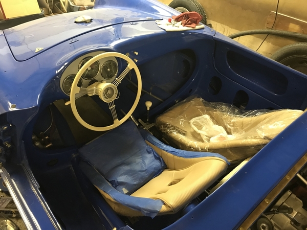
Installed Gordon's 5-Cent Racing fuel gauge calmer-downer thingie (thanks again, @Gordon Nichols) and tested my sender with the gauge.IMG_4128IMG_4129

Bent the sender arm a bit and, using a bit of wire to manipulate it in situ (thanks @Alan Merklin) got it so it shows empty just right but with the tank full it reads just under full. I may bend it just a little more to make it read full on full and empty just a little before it's really empty. 

The calmer-downer thing did not noticeably affect the swiftness of the needle's movement but I chalk that up to the kind of jerky way the sender gets moved on this test.

Did a little more welding on my beam gussets and painted the bare metal black. This photo obscures the truly atrocious spatter and blobs I made with the welder, and I'm totally OK with that.

IMG_4126

Finished alignment today and to my surprise and joy, I was not obligated to drill or saw on the torsion arm holes. Toe in front is 1/8 inch, rear about 3/16, front camber about 1/3-1/2 degree negative on both sides, rear camber is about -1. Here's the toe measurements I got before checking the overall front-to-rear squareness.

IMG_E4131

Yesterday I wasn't sure how I would do it. Today I rummaged around the scrap pile and found an old bed frame. Set one side across the lift, snug up to the front of the front wheels. The other went behind the rear wheels....

IMG_4132

The initial measurements were not encouraging: Almost half an inch longer on the driver's side.

IMG_4134

IMG_4135

The left rear wheel was already kind of tight forward in the wheel well, and some earlier toe-in measurements had left me with the impression that I was going to be out of adjustment before I got it in spec. But it turns out the slots are long enough.

Right side back 3/8 or so...

IMG_4136

Left side forward a bit less than that:

IMG_4137

Check toe again...

IMG_4138And...

IMG_E4139IMG_4141

Front/rear wheel base length is maybe 1/16-inch off side to side, slightly longer on the right which maybe is good because it should bias the car to a slight left turn to counteract road crown(?).

Rear ride height is a hair more than 5.5 inches and front is about 5.65; 60 lbs fuel in front and the spare in back should bring it very close to even at 5.5 inches all around when underway.

Alignment done, I returned to the hydraulics.

Passenger front caliper may be leaking. Wiped away some and pumped the pedal, will check later for wetness. The clutch still doesn't work & I'm almost out of adjustment on the slave cylinder. No air on the bleed. I'll dig into it again tomorrow but curious to hear from fellow Spyder people running the CNC hydraulics.

Attachments

Images (14)
  • IMG_4111
  • IMG_4126
  • IMG_4128
  • IMG_4129
  • IMG_E4131
  • IMG_4132
  • IMG_4133
  • IMG_4134
  • IMG_4135
  • IMG_4137
  • IMG_4136
  • IMG_4138
  • IMG_E4139
  • IMG_4141

On alignment: I use jackstands and string touching the tires at hub level to set toe, front and rear. On my car the front track is a bit wider than the rear, so it does take a few minutes and some adjustment to get them straight. I don't need to tell you this, but always set camber first and toe last. Camber changes toe, but toe doesn't change camber.

On the clutch, you may need to tighten the slave a bit. Physically push the clutch cross shaft lever until you feel it touch the throwout bearing, then back off a tiny bit. That tiny bit at the slave will translate into almost an inch at the pedal. Are you using a 5/8" master and 3/4" or 7/8" slave? What is your pedal/MC pivot ratio.

Post Content
×
×
×
×
Link copied to your clipboard.
×
×