I saw that the Kitman topic was closed, but wanted to provide an update on my progress.  Three big issues have come up (so far):  1) The rear body mount as provided is a large U shaped bracket that bolts to the transmission mounting bolts - which makes installation a challenge, but doable.  Unfortunately, it can't be installed once the body is on the chassis - it is too long.  I cut the bracket and sleeved it which solved the installation problem and then fabricated a vertical bracket at the rear that seemed to work, but then discovered that the mount interferes with the exhaust.  I have spent the last couple of weekends fabricating an alternate rear mount such that the exhaust header can also be installed, but I am concerned about the weight/leverage on the trans bolts....2) The doors do not seem to fit.  If properly aligned at the front seam, the door is about an inch out at the bottom rear.  It is not out of the question this is operator error, but the problem seems to be the same even when placing the door in the opening with no hinges....Chris Kleber suggested I may have mounted the body incorrectly, but I don't know how that could happen....3) a stock fan shroud will not work as it interferes with the engine cover structure.  I hope I have solved that problem with a lower profile shroud but still waiting to get the engine cover mounted (see below).

One smaller issue I am dealing with is I have not had any luck mounting the engine cover.  I have tried several hinge/bracket arrangements, and it always seems to bind at the top when opening it.  Any clues?

Thanks.

Original Post

Replies sorted oldest to newest

Dave - I wondered how the FF/CMC build manual matched up to a Kitman build.  Be sure to make notes in the build manual for others who might be so adventurous.

On my CMC with factory mounted doors, the lower rear sticks out about 1/4" on both sides.  The door is made much like a modern car door in 2 pieces that are bonded together. 1 piece is the outer door skin and other the structural piece.  Mine is black gel coat - when/if I paint it I will grind out the Bondo (pink) that CMC used to attached the 2 pieces together - that way I can close where it sticks out.  I'm sure the bonding is the issue on yours.

550 2 door pieces as example - couldn't find image at RustyTubs for 356.

Porsche 550 door or door set body panel kit car

My hinges were a pain to mount.  Once they opened and closed ok (done before pan was mounted).  The hinges hit the shroud and I had to flip the hinges side to side so they were set wider.  I didn't have issues with the rain shield using a later dog house OEM cooler.  Maybe look for a shorter PUMA shroud or Thing one?

Image result for Puma VW shroud. Size: 185 x 185. Source: www.kijiji.ca

Last edited by WOLFGANG

I assume you purchased the tube inner frame from Kitman too, it would be nearly impossible to rack the fiberglass so much as to cause a 1" door issue.  Post some photos of the issues and we can be of help.......... On a number of my past CMC FF speedster builds, the rear of the doors protruded 3/8" or more . My fix was to cut the 3/8" from the inner panel and 3M Panel Bond it back together.

Last edited by Alan Merklin

I remember instructions manual for the CMC said all holes/cutouts were clearly marked with dimples in the gel coat --- apparently that was the case for those bodies molded several years beforeo - but not in the mold used for mine.  I had to call about mounting the windshield posts.  I received a rough drawing faxed to me at work.  I measured and there was a difference in measurements side to side!

Last edited by WOLFGANG
@WOLFGANG posted:

I remember instructions manual for the CMC said all holes/cutouts were clearly marked with dimples in the gel coat --- apparently that was the case for those bodies molded several years beforeo - but not in the mold used for mine.  I had to call about mounting the windshield posts.  I received a rough drawing faxed to me at work.  I measured and there was a difference in measurements side to side!

There were three CMC classic molds A,B,C . The A did have the dimples in the Gelcoat on early production bodies but there was never a marked location for the windshield post location. Now days I can point with my finger where to drill the 5/8" hole in the top of the fender .

So here are a couple of pictures of the the door gap and a couple my newly fabricated rear body mounts with cutouts for the exhaust.  I am resigned to trimming the door and I feel sure that will fix that problem.  I may not want to tackle that myself though.  Jury is still out on my rear body mount.  In the pictures you can see how I cut and sleeved the mount that came with the kit and which extended to the very back of the body.  As provided by Kitman there was no way to install it after the body was on the chassis.  It may have been possible to install the mount first and then somehow slide the body over it, but I didn’t have enough willing friends to try that.  Then, I discovered that the exhaust headers on the front of the  engine (relative to the car) were obstructed by the mount.  Back to the drawing board!  The pictures show what I came up with - while not super proud of my welding skills, but I am good with a grinder!.  No matter what, this seems like a lot of weight and leverage on the trans mounting bolts.  I think CMC had a portion of the main (welded) frame extend toward the rear of the car which seems like a far better solution.

I welcome feedback.

Dave

Attachments

Images (4)
  • 7EFBBC31-D199-477B-AC88-5E8229CDB6F5: Right door gap
  • 005C307A-303B-41E2-BDA4-31F8EB3381AA: Right door gap again
  • 5D9541BA-2CFF-48C3-B1A5-FA0C1D2348C0: Right rear body mount
  • 428F6F28-6B21-4F2D-AF2B-C1CC558401C0: Left rear body mount

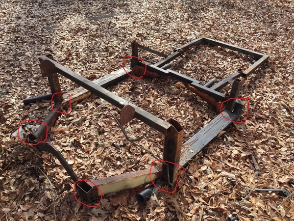
Here's a bare CMC sub-frame from a burnt up Speedster (ignore red marks).  The square tubing to the rear is not very strong and relies on a few rivets to it to support the tail fiberglass (hence butt sag with a bigger gap at rear top of doors (easy fix).  I like the way you moved it back.  With a T1 engine the transmission/frame horns and an add-on Kaffer brace will handle a good size engine (if frame horns don't have internal rust).  The rear brace would be handy for hanging a heavier type 4 engine or a Subaru rear mounting point.

speedster frame points

Without door strikers installed, will your door close further? Mine are only stick out for a few inches up the door (maybe 4-5 max).  Or do you have rubber seal installed pushing it out?  Alan for sure has an idea.

Attachments

Images (1)
  • speedster frame points
Last edited by WOLFGANG

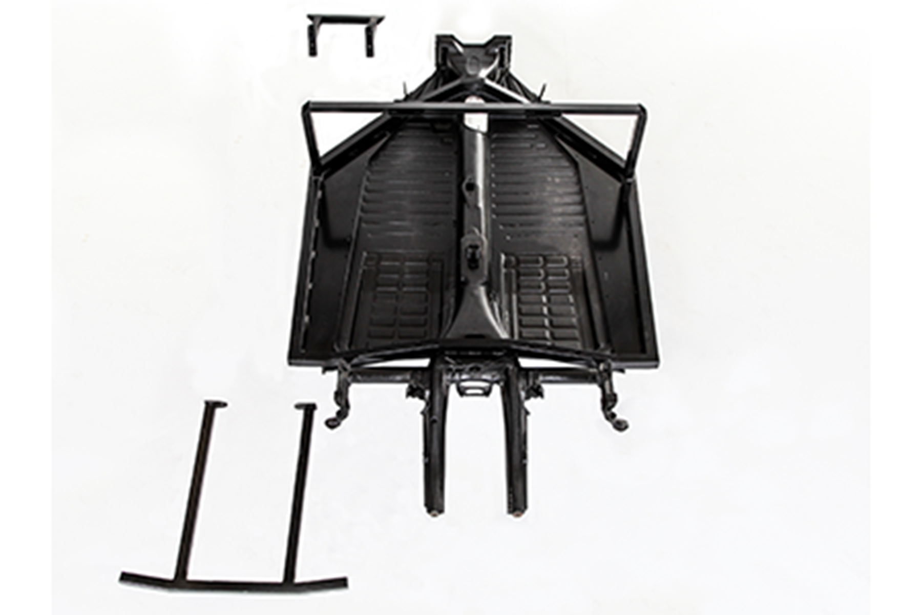
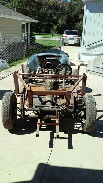
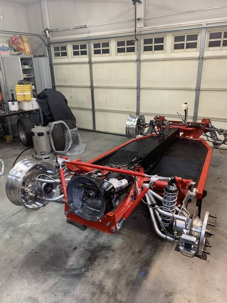
When I look at the Kitman frame - it looks less robust than the CMC frame.

KitMan Motors VW-Pan-Based-Chassis

The around the interior cabin part of the CMC is like 3x4" steel.

speedster subframe

The part to the rear is about the same but the CMC has welded posts behind door for the show bar mounting (which many use to run more steek to the back to correct butt sag.  I would complete the boxing in of the area where you added strips.  I would also consider adding gussets wherever possible.  Believe near all CMC came with the subframe bonded and riveted to the fiberglass body (save shipping volume and gives rigidity to body during handling.

Attachments

Images (1)
  • speedster subframe
Last edited by WOLFGANG
@Nadodave posted:

...   Jury is still out on my rear body mount.  In the pictures you can see how I cut and sleeved the mount that came with the kit and which extended to the very back of the body.  As provided by Kitman there was no way to install it after the body was on the chassis.  It may have been possible to install the mount first and then somehow slide the body over it, but I didn’t have enough willing friends to try that.  Then, I discovered that the exhaust headers on the front of the  engine (relative to the car) were obstructed by the mount.  Back to the drawing board!  The pictures show what I came up with - while not super proud of my welding skills, but I am good with a grinder!.  No matter what, this seems like a lot of weight and leverage on the trans mounting bolts.  I think CMC had a portion of the main (welded) frame extend toward the rear of the car which seems like a far better solution.

I welcome feedback.

Dave

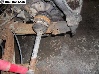
I do not think the rear mount, that apparently is bolted on by the trans bolts, is a good idea.  That is one helluva moment arm on the frame horns.  The frame horns were designed to support the engine and trans, but I would not want to add the extra load, especially extended out so far.  Actually, many folks (myself included) add a kafer brace to help support and stiffen the frame horns.  This is an indication that the horns are not a tremendously strong part of the frame.

I would attach a rear mount that is designed and attached more like the CMC frame.  It could be welded/bolted to the subframe on each side and form a u-shaped support frame around the rear of the engine compartment.

Thanks for the feedback everybody.  I'm not an engineer (I played one in the Navy!), but I was/am concerned about the weight and twisting moment of the brace on the frame horns.  I think I am now resigned to jacking the body up enough to weld a substantial rear body brace to the Kitman subframe.  For James - is this what you are referring to for a kafer brace: https://www.coolrydescustoms.c...afer-bar-system.html.  Thanks again everybody.  I may not be the first to do a Kitman (at least this far), but it is more challenging than I expected!

That link doesn't work, Dave, although that Mendeola Brace (the "Stiffy"?) is supposed to be a tad stiffer, if that's important to you.  So to compare, here's a Kafer Brace at JBUGS:

https://www.jbugs.com/product/...Kx4D_ghoCl-oQAvD_BwE

And the one I use from CB Perf:

https://www.cbperformance.com/product-p/4501.htm

Either one works the same, either one can be pre-loaded, slightly, and all three should work great.

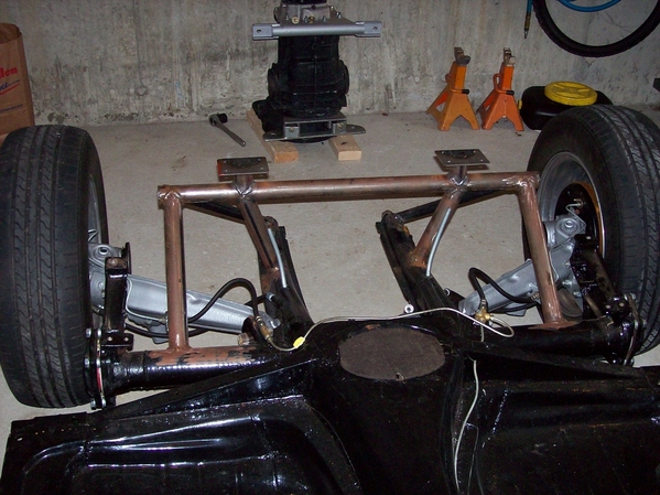
Here is what I did on a 1958 Karmann Ghia.  This triangulated the frame horns and tied them into the torsion tube. This work out very well. I’m sure you could do something similar and tie it in to the rear subframe.  If you try this, put the transmission rear mount on before you weld on the  frame horns, as the  heat will move them!  I also used this to tie into a roll ball, that is the upper plates in the picture.C2A28F3C-796F-4DF7-876A-2B83F40B3452

Attachments

Images (1)
  • C2A28F3C-796F-4DF7-876A-2B83F40B3452
@Nadodave posted:

For Li-Rick:  As I mentioned above I need to fab a rear body brace for my Kitman Speedster.  It had not crossed my mind that I might be able to cantilever it on the torsion tube.  Any issues with welding on the torsion tube?  I envision welding a bracket on the torsion tube and then bolting a cantilever arm to it to support the brace that is welded to the subframe.

Thanks in advance.

No problem welding to the torsion tube. That is the strongest piece of steel on the whole chassis. Make sure you get good penetration on your welds and use tube of sufficient diameter and wall thickness. I used 1.5”  x  3/16” wall.

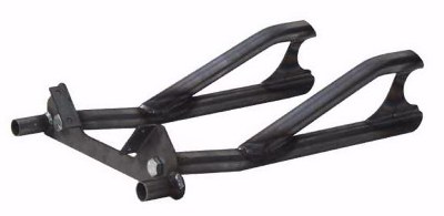
Fortunately, they sell an aftermarket frame horn assembly for reasonably money the issue is you need to construct a temporary jig so that you get the correct factory orientation but if, you frame horns are severely rusted you can count on them not being in the precise location as from the factory.                                        https://acmecarco.com/store/in...;sort=20a&page=3

TUBULAR FRAME HORNS KIT

Last edited by Alan Merklin
Post Content
×
×
×
×
Link copied to your clipboard.
×
×