I definitely need to make one of those. Drawings would be awesome.
PM'd.
The speedster ones are still available commercially.
Carey makes these now as well.
I've always thought those latching hinges were pretty slick.
It's amazing, Ed, that you were able to cut out some simple shapes, put them together, and actually make them work as intended.
The thought that went into the original design is impressive. How did they come up with something like that out of thin air? How many other builders would have bothered? I guess the hinges are a tiny example of the design principles at work throughout the whole car - how to do more with less.
Keep up the good work. Your detailed progress reports are revealing parts of that design that many of us would otherwise never get to see.
Thanks, Mitch.
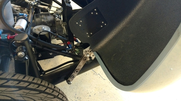
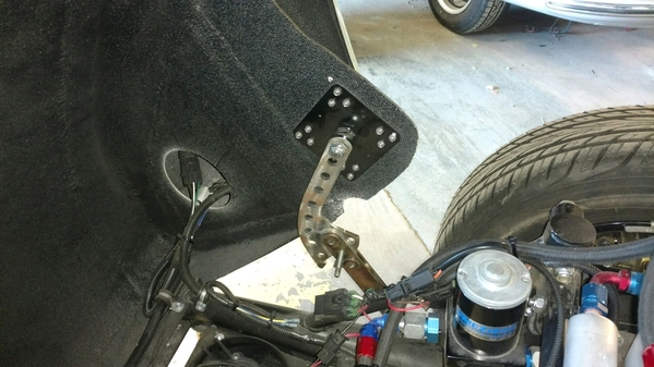
Here's the Beck part, which (last I checked) was a $350 option on your build, $250 out the door. It's a beefier part and a stronger design than mine (albeit not-quite-period-correct), with a couple pounds weight penalty. If I had a job I'd probably have bought it rather than spending the 13 or so hours copying the original part, enjoyable though they were. It helped too that I already had the perfect piece of 1/4-inch thick aluminum plate and a big sheet of 1/16 stainless just loitering around the scrap pile, so my material cost is only about $4 in fasteners. Your mileage may vary.
Attachments
Yeah, that's the one I have on the new car. It really looks the part, and yes, it's steel. It isn't that heavy, though. It is VERY cool you made yours from aluminum. And by hand no less!
I painted mine with hammered silver, to look more vintage. I really like the way all the parts look with that finish on them.
I drilled an extra hole in mine for a lock pin I keep in the driver's door. I worry that one day at a car show the wind will hit it just right and lift it up enough then SLAM down it goes. Or somebody will lean on the clam and mistakenly push it up, then SLAM! So now I don't worry at all, just slip the hitch pin in and lock the bail.
Interesting, given the pic shows a bolt through it. He must've added that after you got yours.
I had the same concern; added the lock pin to mine the other day. Re-used the chains that came on the door handles Carey sent me. I'll probably rivet the chain end in next to the clam stay, and drop the pin in one of the spare tire mount lightening holes for storage. Then it's right there when I pop the clam open.
BTW, here's what's next:
Attachments
Nice, I have some of that too but never installed it. I think I have 6 feet or so, but it's used so not all pretty like yours. I was going to attach it to my trailer hitch for when I flat tow the Spyder, but never did.
Good luck installing that around the suspension, it looked like too much of a PIA to me. Are you doing the full engine undertray as well????
I plan to make an undertray but that job really is for after the wiring and plumbing and painting is done. Brush guards are installed. Clam latches and cable remote too, but the passenger side is sticking open. Could you (Danny) send me that pic of your double-spring rig again?
Attachments
Clam lid now latches tight and unlatches with the flip of a lever. We're getting down to brass tacks.
Attachments
Looking good Ed.
Been away from the project for a few days. Itching to get back into it. Updates soon...
Back at it today. I made the throttle linkage that goes on the firewall (changes direction of the cable-pull and makes it a "push," per the original). Also put a throttle stop in my gas pedal rig. And I cut out a set of seatbelt mounting tabs to weld in to the chassis.
Attachments
Got my seat belt anchors welded in today.
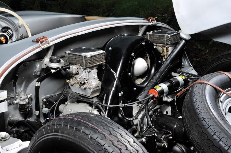
Also roughed-in the two main hard fuel lines, including (of course!) the period-correct Italian-made glass bowl fuel filter/pressure regulator (apologies to Stan).
Attachments
Wow Ed, "U Da Man" some awesome work you've been doing.
Pete
Thanks, Pete.
Oh yeah, we're into the fun stuff now.
...apparently the above is wrong because there is no "bubble adaptor" on the clutch mater cylinder. Two such adaptors were supposed to be supplied "with the kit," according to the build manual, but none were.
Anyway, I am enjoying learning the finer points of SAE/NPT vs Metric flare standards...Anyone wanting to accelerate my learning curve, I'm all ears.
Attachments
No matter what you have , how much you have .....you never ever have the right fitting...It's called Ed's Law :~)
Wilwood uses 1/8" -27 for all their stuff. So you need a metric female(10mm x 1.0 I think) to male 1/8 pipe thread adapter.
If you do the AN flex hoses, they are AN-3 usually and they have adapters on the ends. Some guys will tell you that they must be done with no adapters but they work fine. You can get hoses in any length you need, I used Pegasus Racing. They also have any adapter you could possibly want. Pipe thread, male/female, bubble, 45s, 90s, banjo ends, all of it.
I cheated. I used a guy in town that had all of the stuff needed to make any connection you had and he did it for a living. Same guy that did "Tubes and Hoses". Ask the NAPA guys - they'll probably know of a shop near you.
Thanks, all. I flared a bunch myself today and roughed-in all the hydraulics.
I found one adaptor in the coffee can fulla brass junk I bought from Merklin last year, and maybe that was all I needed.
Then again...we'll see when I fill the clutch reservoir and try to bleed it, I guess.
Attachments
Just make sure your brake pressure switch for the brake lights is screwed into the proper port, and that one of the front wheel lines ISN'T in the switch port!
Oh yeah, and install two switches(and make the wires long enough to reach either), because it isn't a matter of if it will fail, it's when.
Ah... Good point. TR Manuel says block the front top port but of course that's the second front brake line port, isn't it? And the two midline ones are for two brake light senders.
Keep those advisories coming, gentlemen.
The brake line ports are larger, the pressure switch ones are tiny. Look at it, you'll see what I mean. Been there, done it wrong, went back and fixed it!
As a man, I seldom consult the instruction manual, and here's Exhibit A as to why!
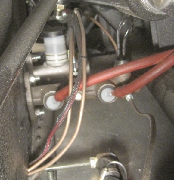
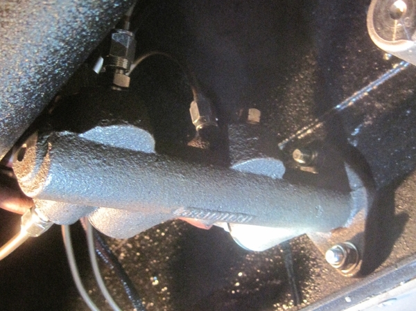
Whelp, the ports in this MC all appear identical. Mine has the number 113611015BD cast into it and the words "USE THIS" sharpied on the other side. Looks like this one, which is a 20.6mm 4-wheel disc conversion MC.
Think I'll move that left front wheel line to the top port, screw signal switches in the middle ports and call it good for testing.
UPDATE: on closer inspection, three of the five ports appear to be restricted: down inside the small hole you can see there's a smaller hole.
So the bottom ports, front and back, are "large" (unrestricted) while both middle ports and the front top port have the smaller holes.
I have seen photos of VW MCs rigged up all over the internet and I don't think I've ever seen a T fitting on front brakes. Always two ports. But if my MC is typical, always one of those ports would be flowing about 1/3 what the other flows.
UNLESS the large ports on the bottom are exclusively for the switch?
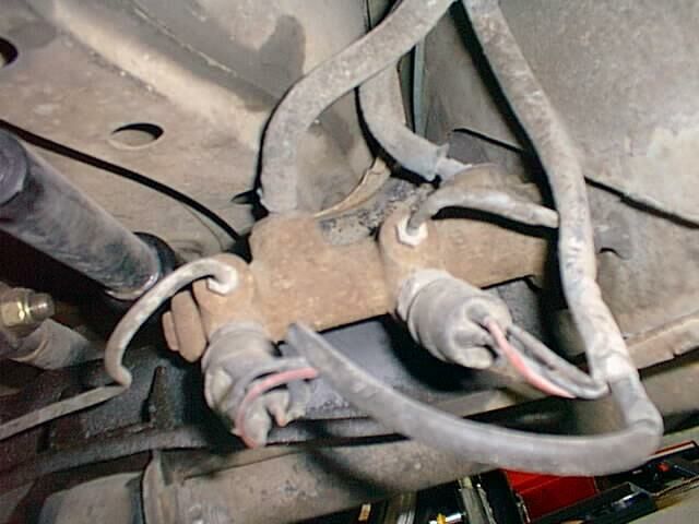
Man, I'm dumb.
Attachments
you mounted it sideways! I didn't even know you could do that.
Thanks.
Next order of business: Those with the Fibersteel (or similar) original 550-style E-brake: how do you route your cables and/or through what and/or what is the cable pn?
Just got out the cables from the kit and I believe they are standard swing axle bug cables. They fit the brakes neatly but appear on the short side. Do you-all have extenders? What's the end hardware that interfaces with the stick?
More significant: most of the cable is unsheathed. There's no way to get from the brakes to the firewall with the sheathed part, so the cables would tend to saw through whatever you routed them through.
Looks like the way forward is to get a 1/2-inch steel pipe or tube (conduit, maybe?), Y it into the firewall and extend it to the flexible sheath in such a way that it won't interfere with the engine/exhaust, etc.
But before I start, I'd love to see how some of you have yours routed. This is particularly true if I'm thinking wrong.
I didn't mount anything, it came like that. But, it does make it easier to replace the brake light switch when it does fail. I didn't have to rebleed the system when I replaced mine. I did add a few drops of fluid to the hole and I prewet the business end of the switch before I installed it though.
My E-brake cables run through two steel tubes from the cockpit, through the firewall then left and right along the firewall, then they turn down the frame towards the brakes. I can send pictures, but If your trying to duplicate what they did back in the day, it might be better to find some vintage shots.
"Looks like the way forward is to get a 1/2-inch steel pipe or tube"
Maybe 3/8" steel brake line from NAPA? Easy to bend and easy to weld.
Thanks Carlos and Gordon. Def would like to see pics.
So I found the threaded rod that came with the e-brake handle; shortness of cables is not longer an issue.
In the box was also a piece of steel pipe that just fits over the flange ends of the cable sheathes. I already cut a little off to make something or other, but it looks like easy to find stuff. Harder to bend than 3/8 brake line though; hoping I won't have to bend much.
I've used 3/8" steel tube from Lowe's etc. when I needed to replace cable tubes
You know........Every day is like Christmas at Ed's shop with all of the stuff he keeps finding.
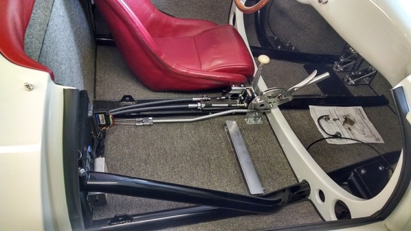
This is what my car looks like. It's a coil spring instead of a torsion spring like yours, so I have a little more room in that area. You also have more of a fiberglass shelf than I do. My rear hydro brake lines also "T" at the firewall, which I think is typical.
I would like to redo my fuel line situation in the near future. Lessen some of the rubber hose. I also prefer the spring clamp versus the worm drive clamps. I also need to shield my clutch hydro line in a spot where it gets pretty close to the exhaust.
Where the two tubes come through the firewall, I would've liked them to have been stacked vertically instead of side by side, and a little closer to the center of the car. This would make for a little more clearance with my passenger seat.
When I bolted the rear of my seats to the floor, and tilted them back, I had to make a metal shield so the turnbuckle on the cable adjusters wouldn't tear up the leather on the seat. This might be a point of interest for you since you have the opportunity to correct this, if it applies to your seating situation.
I think your seats will be farther off of the floor than mine are, so you might not even have an issue.
Attachments
HUGELY HELPFUL! Thanks. This is just about what I was thinking, but getting confirmation makes it a lot easier to proceed.
Ed, I believe the ports you want to use are lined up with the fluid input ports and 90 degrees to them. The ones at a 45 degree angle are for the brake switch or switches. I think one of mine is plugged and I only have one switch.
With respect to the rear e brake tubes, mild steel is fine. You can bend it quite easily if you heat it to a warm red with a MAPP torch and bend very slowly along as you move the heat. Heat the inside of the curve more than the out. MAPP gets hotter than straight propane. I hope these pics help, I don't have a good one of my MC.
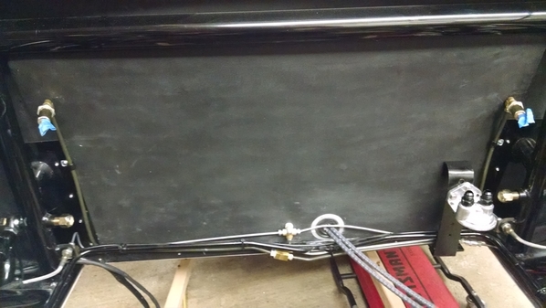
Fuel lines are on the bottom, then the clutch line, the ebrake tubes, then the brake T on top above the shifter cables. You can see the metal fuel lines going up the firewall with my backwards Ford filters(with nitrile condoms!). Like Carlos, I prefer minimal hose(German woven cloth) and I used the spring clamps. Not a single worm clamp in the fuel system.
I made a T from aluminum for the Ebrake and welded some 1/4-20 nuts to the tube on both ends. It works well, keeps it low and away from the seat.
Attachments
In the last picture you can see the aluminum angle I used to lift the front of the seats up.
Also very helpful, thanks. I can see your seat belt anchors are about like what I made too.
Again, I say: seeing these details on other cars—cars I know are done well and that work—means the world to me.


